


We get a version of the same panicked message every month at NPHIS: “The strip arrived, we wired it exactly like the datasheet, and half the run is dead.” Nine times out of ten, the real issue isn’t the LED strip. It’s a mismatch buried inside the question of DMX pixel decoder vs standard DMX decoder — two boxes that look almost identical on a spec sheet but speak completely different electrical languages on the output side.
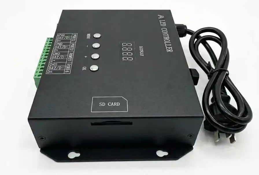
Table of Contents
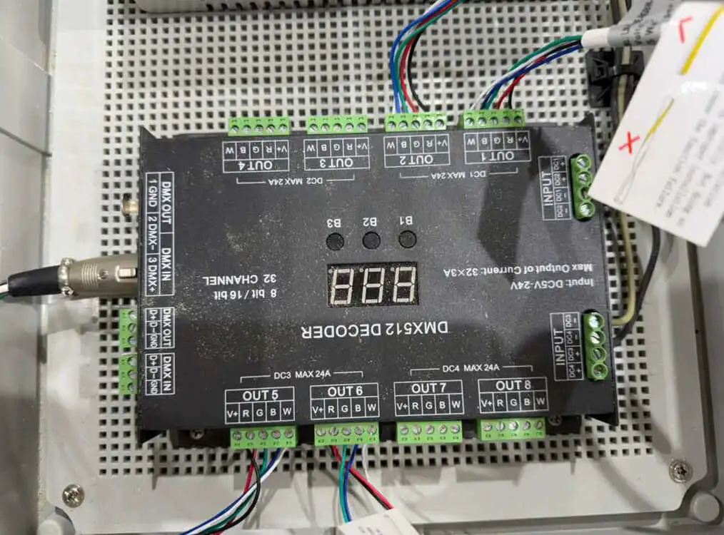
We see this failure mode every week on our support line. An electrical contractor finishes a 100-meter linear LED installation for a retail flagship or an event stage. They power it up. The strip either stays completely dead, or it flashes through random colors with no pattern at all. The client is standing right behind them.
This guide walks through exactly why that happens, how to choose the correct decoder before you order, how to diagnose failures on-site in under ten minutes, and how to commission the system correctly the first time.
Why Your Addressable LED Strip Fails With a Standard DMX Decoder
Let’s start with the fault itself, because most readers land here mid-crisis after searching addressable LED strip not lighting up DMX decoder.
A standard decoder was never designed to talk to a strip with onboard ICs. Wire the two together and three things happen simultaneously:
- The ICs get power-cycled. The decoder chops the ground path thousands of times per second. Digital pixel ICs need a clean, constant DC rail to hold their programmed state — rapid ground switching resets them instead of dimming them.
- No data ever arrives. A PWM decoder has no serial output stage. The strip’s DATA pad sits waiting for packets that will never come.
- The reference floats. If grounds aren’t bonded, any segments that do wake up will flicker randomly, because the data line has no stable 0V baseline to measure against.
The strip was never broken. The protocol was.

DMX Decoder vs Pixel Decoder: The Core Difference
These are not two versions of the same product. They are two different control philosophies.
The Standard DMX Decoder: An Analog Dimmer With a Digital Front Door
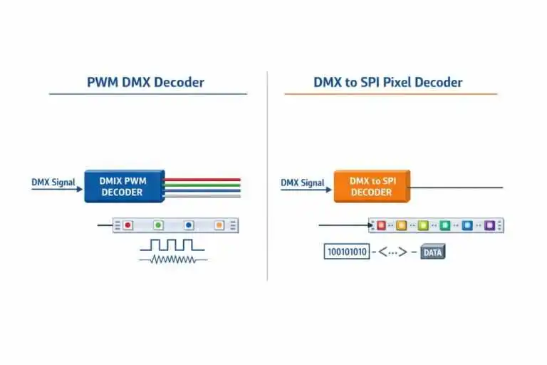
A standard decoder listens for a DMX512 command, then drives a bank of MOSFET switches that rapidly cut and restore the ground path to the strip — that’s Pulse Width Modulation (PWM). The LED chips have no idea a decoder exists. They see a constant V+ rail and a ground being switched faster than the eye can register.
This is why a standard decoder can only ever control a zone, never an individual pixel. Every LED on the circuit shares the same ground path, so they all dim and shift together.
The Pixel Decoder: A Real-Time Data Translator
An addressable strip works on the opposite principle. Each tiny IC on the PCB receives constant DC voltage plus a data stream. The IC reads its own instructions, latches the correct RGB value, and either passes the remaining data downstream or listens for its own address on a shared bus.
The pixel decoder’s job is to feed those ICs the exact digital dialect they expect — not modulated power.
PWM vs SPI Architecture Explained: The Telephone Game vs. The Mail Carrier
This is the heart of the DMX PWM decoder vs SPI pixel decoder question, and we explain it to every new contractor client with two mental pictures.
Raw SPI pixel data behaves like a game of telephone. Each chip must receive the clock and data cleanly, then relay it to the next chip in line. If chip #40 in a run of 200 is damaged, everything downstream goes dark — the “message” never gets passed along.
A DMX512-compatible parallel addressing IC, like the UCS512H4L family we manufacture with, behaves like a mail carrier walking a street of RS-485-connected houses. Every IC sits on the same asynchronous bus and listens for a packet addressed specifically to it. A damaged unit doesn’t block the bus — the carrier keeps walking and delivering mail to every other house on the route.
That single architectural difference decides whether your installation survives a mid-show pixel failure — or blacks out an entire section in front of the client.
How a DMX to SPI Converter for LED Strip Bridges the Protocol Gap
A DMX to SPI converter for LED strip installations is, at its core, a small dedicated microprocessor. It intercepts the incoming RS-485 DMX packets, parses the channel values addressed to it, and re-generates a brand-new, clock-synchronized SPI output — matched in timing and voltage to whatever pixel IC family the strip uses. It translates between two protocols in real time; it does not simply pass a signal through.
Before you add a converter to a bill of materials, confirm three things with your supplier:
- IC compatibility — the converter must support your exact chip (WS2811/WS2812B, APA102, UCS1903, TM1814, and the UCS512 family all clock slightly differently).
- Control mode flexibility — look for both Direct Pixel Mapping (full video-style content) and Macro Dynamic Effects (built-in chases that save entire universes on simpler installs).
- Electrical protection — CE, EMC and FCC-rated units cost slightly more but prevent exactly the crosstalk and noise issues that cause ground-loop failures in the field.
Technical Comparison Matrix: Standard PWM vs. DMX-to-SPI Decoders
First, do the channel math — it’s the fastest way to catch a mismatch before hardware ships.
One DMX universe carries exactly 512 channels per the ANSI E1.11 DMX512-A standard maintained by ESTA. A standard RGB pixel consumes 3 channels:
170×3=510 channels (170 RGB pixels, 2 channels spare)170×3=510 channels (170 RGB pixels, 2 channels spare)
Add a white channel (RGBW) and the ceiling drops:
⌊5124⌋=128 RGBW pixels per universe⌊4512⌋=128 RGBW pixels per universe
This is exactly the arithmetic error that gets missed on a rushed quote and shows up as “dead pixels at the end of the run” three weeks later on-site.
| Comparative Parameter | Standard Constant-Voltage PWM DMX Decoder | DMX-to-SPI Smart Pixel Decoder |
|---|---|---|
| Input Protocol | Standard DMX512 (asynchronous RS-485) | Standard DMX512 / Art-Net / sACN |
| Output Hardware Signal | Multi-channel constant voltage PWM (GND switching) | Synchronous digital serial SPI (Constant V+, Data, Clock, GND) |
| Control Resolution | Global strip-wide zoning | Individual pixel or pixel-group customization |
| Max Distance | Up to 1,200m (shielded twisted-pair) | Output data line < 1–2 meters |
| Primary Failure Risk | Thermal overload of switching MOSFETs | Ground loop noise, signal line crosstalk |
| Target Load | Standard RGB/RGBW strips (no ICs) | Individually addressable pixel strips |
Need help matching your LED strip and DMX controller?
Skip the guesswork. Send us four details:
- IC model
- Voltage (12V / 24V)
- Pixel pitch
- Project size (total meters / pixel count)
Our engineers will recommend the correct control solution — usually within one working day.
📧 ted@nphis-led.com | 📱 WhatsApp: +86 182 1724 1063
DMX Pixel Decoder Selection Guide: How to Choose the Right Decoder for Your LED Strip
If you’re wondering how to choose a DMX decoder for LED strip projects, work through these four checkpoints in order. This is the same qualification sheet our sales engineers use on every inbound RFQ.
Checkpoint 1: Does Your Strip Have ICs?
Look at the PCB. If you see small black chips between the LEDs, or a pad marked DATA/DAT, it’s addressable — you need a pixel decoder or a strip built on a DMX512-compatible intelligent LED driver IC. If the pads read only V+, R, G, B (W), it’s a standard analog strip — a PWM decoder is correct.
Checkpoint 2: RGB vs RGBW DMX Decoder
Choosing between an RGB vs RGBW DMX decoder comes down to channel count and white quality:
- RGB (3-channel): color-mixing only; “white” is a blend of R+G+B — acceptable for facades, poor for retail interiors.
- RGBW (4-channel): a dedicated white chip gives true high-CRI white plus saturated colors — but each pixel eats 4 channels, cutting universe capacity from 170 down to 128 pixels.
Rule of thumb: if the space is occupied by people (hotels, retail, hospitality), spec RGBW. If it’s viewed from a distance (facades, bridges), RGB is usually sufficient.
Checkpoint 3: DMX Decoder Voltage — 12V or 24V?
Match the decoder’s output rating to your strip. On the DMX decoder voltage 12V 24V question:
- 12V: fine for short runs and tight bend radii; higher current per watt means more voltage drop.
- 24V: our default recommendation for commercial work — longer runs between feed points, roughly half the current, cooler MOSFETs.
P=V×I⇒at 24V, current halves for the same wattageP=V×I⇒at 24V, current halves for the same wattage
Most quality decoders accept 12–24V input, but always verify the per-channel amp rating against your strip’s actual draw.
Checkpoint 4: Addressable LED Strip Controller Compatibility
Addressable LED strip controller compatibility is where most cross-supplier orders fail. Before issuing a PO, get written confirmation of:
- The exact IC model on the strip (not just “WS-compatible”).
- The converter firmware’s supported IC list.
- The color channel order (RGB vs GRB vs RGBW mapping).
- Data voltage level — some 5V-logic ICs need level shifting on 24V systems.
At NPHIS, we sidestep this entirely by pairing every addressable strip order with a factory-verified matching controller — one signed compatibility note, one throat to choke.
What We Check Before Shipping Every Addressable LED Strip Order
Fixing failures on-site is expensive. Preventing them at the factory is cheap. That’s why every addressable strip order that leaves our facility goes through the same six-point pre-shipment verification, signed off by an NPHIS engineer:
- ✓ IC model — physically confirmed against the PO, not just the batch label
- ✓ Voltage — strip rating matched to the specified decoder output (12V/24V)
- ✓ Pixel pitch — counted and verified against project drawings
- ✓ Controller compatibility — strip tested live on the exact controller model the client will use
- ✓ Color order — RGB/GRB/RGBW channel mapping confirmed and documented
- ✓ Aging test results — 12-hour continuous burn-in report attached to the shipment
Each shipment includes this signed checklist. If a mismatch ever surfaces on-site, you have a documented baseline to diagnose against — and one factory accountable for it.
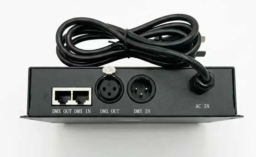
NPHIS Pre-Shipment Verification — Every Addressable Order
- IC model — physically confirmed against the PO
- Voltage — matched to specified decoder output (12V/24V)
- Pixel pitch — verified against project drawings
- Controller compatibility — tested live on the client's controller model
- Color order — RGB/GRB/RGBW mapping documented
- Aging test results — 12-hour burn-in report attached
Common Wiring Failures We See From the Factory Support Line
Based on our support tickets over the past two years, these five faults account for the overwhelming majority of “dead strip” calls:
- PWM decoder driving an IC strip — the classic protocol mismatch covered above.
- Floating ground between PSUs — flicker, color jumps, random resets.
- SPI data run too long — anything past 2 meters degrades fast.
- Unterminated DMX line — reflections corrupt frames, worst on daisy-chains.
- Duplicate or gapped start addresses — sections mirror each other or ignore commands.
Every single one is preventable at the design stage. Which brings us to the checklist.
Field Troubleshooting Checklist: Wiring and Commissioning in 5 Steps
Print it. Laminate it. Tape it inside your rack.
Step 1 — The 80% Power Budget Rule
Never load a power supply past 80% of rated output:
PPSU≥Pstrip0.8PPSU≥0.8Pstrip
A 300W run needs at least a 375W supply. Thermal derating in enclosed ceilings makes this non-negotiable.
Step 2 — Shared Common Ground
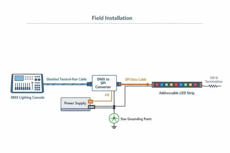
This single step resolves more flickering complaints than any other fix on this list. Console, converter, and strip must share one common ground reference, bonded at a single star point.
Step 3 — Shielded Cables
Use genuine shielded CAT5e/CAT6, never unshielded patch cable from a network closet, and never in the same conduit as AC mains. The shield drains induced noise to ground instead of letting it corrupt the data stream.
Step 4 — Minimize SPI Distance & Terminate the DMX Line
Keep converter-to-first-pixel under 2 meters. At the far end of every DMX chain, fit a 120 Ω120 Ω resistor between Data+ and Data− — as specified in the DMX512-A standard — to absorb reflections.
Step 5 — Address Coding for Parallel ICs
For UCS512-family strips, write and verify each segment’s start address on the bench, before installation. Leave address headroom so one miscoded unit doesn’t shift every downstream address out of sync. Addressing on a bench takes minutes; addressing on a lift takes days.
Factory Engineering Case: Diagnosing an Event Production Mismatch
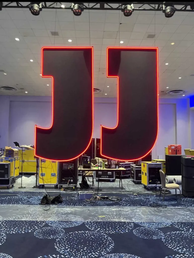
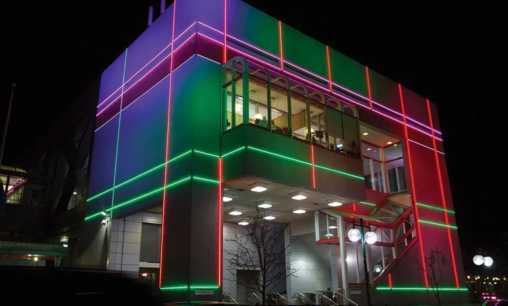
One recent project we supported involved a large-scale outdoor stage backdrop built with our custom UCS512H4L addressable LED strip — 24V RGBW, spec’d for pixel-level color chasing from a professional lighting console.
The Failure
The installing contractor, working against a tight load-in schedule, wired the strips into standard multi-channel RGBW PWM decoders left over from a previous static-color project. On power-up: sections stayed completely dark, others strobed erratically. Our support line got the call hours before the event opened.
The Three-Point Diagnosis
Our field engineer walked the crew through the same three checks we run every time:
1. Continuous power interruption. The PWM decoder was power-cycling the strip’s ICs at its switching frequency — resetting them instead of dimming them.
2. Total signal absence. The decoder had no SPI output stage. It was never going to forward data, regardless of how channels were patched.
3. The floating reference. Where segments did flicker to life, the strip’s data ground and the console’s ground were never bonded — a textbook ground-loop error.
The Fix
The signal was re-routed through properly matched DMX-to-SPI converters, all grounds bonded at one star point, and the full run synced to the console on the first test — no reprogramming required, because the fault was purely electrical, not in the show file.
The takeaway for buyers: sourcing strip and control gear from the same factory eliminates this failure class entirely. Our silicone neon flex and addressable strip lines ship with matching DMX512/SPI control options configured before they leave the factory.
The NPHIS Manufacturing Edge for Commercial Lighting Buyers
Your condensed procurement checklist:
- Confirm the IC family in writing before the PO — not just “WS-compatible”.
- Do the universe math: 170×3=510170×3=510 for RGB, 128 pixels for RGBW.
- Match decoder voltage and per-channel amps to the actual strip load.
- Spec shielded cable, star grounding, and 120 Ω120 Ω termination in tender documents.
- Source strip + controller from one factory with a signed compatibility note.
On the manufacturing side: every addressable strip we ship — from COB flexible strip light to custom DMX512 pixel products and silicone led neon light strips — is built on double-sided electroplated PCBs with 70 μm copper foil:
tCu=70 μm≈2 oz coppertCu=70 μm≈2 oz copper
That copper mass keeps voltage drop low across long addressable runs — a common secondary failure mode that looks like a decoder problem but is actually a copper-thickness problem. Every batch then runs a 12-hour continuous aging test before packing, and full OEM/ODM services (custom PCB width, IC selection, pixel pitch, private labeling) are standard for contractors running multi-site rollouts.
Ready to Spec Your Next Project Correctly the First Time?
Send your project drawings, DMX universe count, and IC preference to ted@nphis-led.com or WhatsApp +86 13681792218. Our engineering team will return a schematic layout and bulk quote directly — or start with a quick quote request on our site.
FAQs
❓️ What's the actual difference between a DMX decoder and a DMX-to-SPI pixel decoder?
A standard DMX decoder outputs constant-voltage, ground-switched PWM to control a whole zone of ordinary RGB/RGBW strip. A DMX-to-SPI pixel decoder outputs a clocked digital data stream that controls each individual pixel IC separately.
❓️ Why does my addressable LED strip not light up when wired to a DMX decoder?
Almost always because the decoder is a PWM device with no SPI output stage. The IC needs constant DC voltage plus data — a standard decoder can’t generate that signal, so the strip stays dark or power-cycles unpredictably.
❓️ How do I choose a DMX decoder for an LED strip project?
Check four things in order: (1) does the strip have ICs, (2) RGB or RGBW channel count, (3) voltage match (12V/24V) and per-channel amps, (4) written IC compatibility confirmation from the supplier.
❓️ Should I choose 12V or 24V for a DMX decoder system?
24V is our default for commercial work: half the current for the same wattage, less voltage drop, longer runs between feed points, cooler MOSFETs. Use 12V only for short runs or tight bend-radius details.
❓️ RGB vs RGBW DMX decoder — which one do I need?
RGBW for occupied spaces needing true high-CRI white (hotels, retail); RGB for distance-viewed facades. Remember RGBW cuts universe capacity from 170 to 128 pixels.
❓️ How many pixels can one DMX universe control?
512 channels per universe: 170×3=510 170×3=510 gives 170 RGB pixels (2 channels spare), or 128 RGBW pixels at 4 channels each. Larger counts need multiple universes via Art-Net/sACN nodes.
❓️ What causes ground loop flicker in addressable DMX installations?
Unbonded grounds between controller and strip. The data signal “floats” without a stable 0V reference, and ICs interpret noise as valid commands. Bond all grounds at one star point.
❓️ How far can I run DMX cable vs. SPI data?
DMX over shielded twisted pair: up to ~1,200 m with 120 Ω120 Ω termination. Raw SPI: keep under 1–2 m between converter and first pixel.
❓️ Why does address coding matter on UCS512H4L addressable LED strip lines?
The UCS512H4L is a DMX512-compatible intelligent driver IC that reads its instructions from a specific address inside the DMX packet stream. Duplicate addresses make sections mirror each other; gapped sequences make sections ignore commands. Code and verify on the bench before installation.
❓️ Can NPHIS pre-program DMX addresses and verify controller compatibility before shipping?
Yes. For OEM orders we write segment start addresses at the factory, label each reel, test the strip live on the client’s controller model, and issue a signed compatibility note — so your crew installs without on-site coding.
References & Sources
- ESTA Technical Standards Program — ANSI E1.11-2024, Entertainment Technology: USITT DMX512-A — tsp.esta.org
- Wikipedia — DMX512 protocol overview and RS-485 physical layer — en.wikipedia.org/wiki/DMX512
- U.S. Department of Energy — Solid-State Lighting Technology Research — energy.gov/eere/ssl
WHY I WRITE THIS
About my business
Our company’s main products include LED flexible light strips, rigid light strips, and linear light fixtures, all of which are manufactured in our own factory or in factories we have been cooperating with for many years.
Our services
Our products are primarily mid-to-high-end, exported to Europe and America. We accept OEM & ODM small-batch orders, and also provide sourcing services in China to help our international clients solve problems. Please contact us if you need our assistance with sourcing.
Contact Profile
Name Ted Lau
Brand Name NPHIS
Country China
Model B2B Wholesale only
Email ted@nphis-led.com
Related Posts
Explore essential insights on material durability, IP ratings, and installation for our Silicone LED Neon Flex. Designed for lighting professionals, this guide helps you make informed purchasing decisions for commercial and architectural applications.


Request a free quote
If you have questions or suggestions,please leave us a message,we will reply you as soon as we can!