
Side Bend LED Neon Flex
24 V DC · SIDE BEND SILICONE NEON FLEX SUPPLIER
Specify the right profile for your curved light line
Compare 19 side bend LED neon flex configurations for signs, architectural outlines and decorative details. Select from compact white-light profiles, dedicated 20 m variants, three-side emission and all-black SPI-RGB options.
For contractors, distributors and OEM buyers. Match the cross-section, emitting face, bend route and connection detail before requesting samples or pricing.
24 V DC input · IP67 catalog rating · Fixed white · CCT and selected SPI-RGB configurations
YEARS EXPERIENCE
0
+
GLOBAL CLIENTS
400
+
HOUR LIFESPAN
0
K
COUNTRIES SERVED
40
+
PROFILE SELECTION
Compare sizes and configurations
Choose the profile and variant together. A shared model number does not mean identical length, output, emitting surface or control requirements.
01
STANDARD WHITE
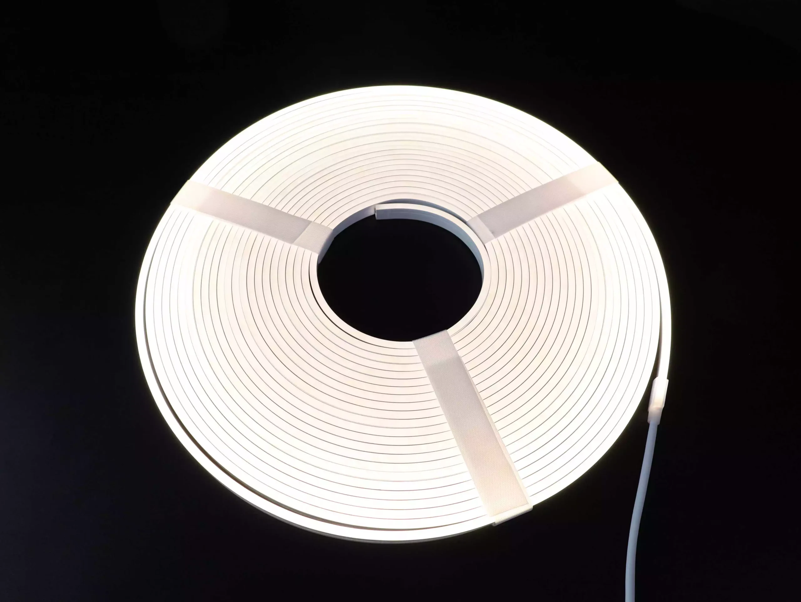
Ten white-light profiles for different recesses
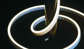
Compare the drawing dimensions, light output and cut interval. The 0817 has a 10 mm maximum width and an 8 mm base; the 1225 has a 15.5 mm maximum width and a 12 mm base. Model numbers alone do not define the mounting fit.
| Profile |
Profile size* W × H (mm) | Light / control | LEDs/m |
Cut (mm) |
Power (W/m) |
Output (lm/m) |
Nominal length (m) |
|---|---|---|---|---|---|---|---|
0408 |
4 × 8 |
White |
168 |
35.71 |
9.6 |
190–320 |
5 |
0410 |
4 × 10 |
White |
120 |
50 |
9.6 |
190–320 |
5 |
0612 |
6 × 12 |
White |
120 |
50 |
9.6 |
235–320 |
5 |
0613 |
6 × 13 |
White |
120 |
50 |
9.6 |
200–330 |
5 |
0817 |
10 × 17 |
White |
120 |
50 |
9.6 |
270–360 |
5 |
1225 |
15.5 × 25 |
White |
120 |
50 |
9.6 |
350–480 |
5 |
1010 |
10 × 10 |
White |
120 |
50 |
9.6 |
320–480 |
5 |
1212 |
12 × 12 |
White |
120 |
50 |
11 |
560–680 |
5 |
1616 |
16 × 16 |
White |
120 |
50 |
9.6 |
320–470 |
5 |
2020 |
20 × 20 |
White |
120 |
50 |
9.6 |
420–500 |
5 |
24 V DC · IP67 catalog rating. White-light options: 3000 K ±150 K, 4000 K ±200 K or 6500 K ±300 K; CRI Ra ≥90.
02
20 M CONFIGURATIONS
Four profiles for longer contours
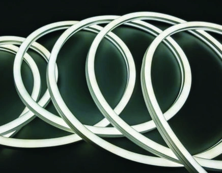
The 0816, 1018, 1020 and 1220 variants are cataloged for 20 m single-end supply using the specified constant-current strip design and copper strips. Confirm the 24 V DC supply, cable size and installation layout for the selected run.
| Profile |
Profile size* W × H (mm) | Light / control | LEDs/m |
Cut (mm) |
Power (W/m) |
Output (lm/m) |
Nominal length (m) |
|---|---|---|---|---|---|---|---|
0816 |
8 × 16 |
White |
120 |
50 |
8 |
210–310 |
20 |
1018 |
10 × 18 |
White |
120 |
50 |
8 |
202–290 |
20 |
1020 |
10 × 20 |
White |
120 |
50 |
8 |
201–302 |
20 |
1220 |
12 × 20 |
White |
120 |
50 |
8 |
145–302 |
20 |
24 V DC · IP67 catalog rating. White-light options: 3000 K ±150 K, 4000 K ±200 K or 6500 K ±300 K; CRI Ra ≥90.
03
THREE-SIDE EMISSION
White light visible from multiple angles
The 1018 and 1220 three-side variants provide a wider visible luminous surface. Their table widths are the dimensioned body/base widths; the projecting luminous cap is wider but is not fully dimensioned in the catalog. Request the full profile drawing before setting the recess width.

| Profile |
Profile size* W × H (mm) | Light / control | LEDs/m |
Cut (mm) |
Power (W/m) |
Output (lm/m) |
Nominal length (m) |
|---|---|---|---|---|---|---|---|
1018 |
10 × 18 |
White |
120 |
50 |
11 |
305–475 |
5 |
1220 |
12 × 20 |
White |
120 |
50 |
11 |
305–465 |
5 |
24 V DC · IP67 catalog rating. White-light options: 3000 K ±150 K, 4000 K ±200 K or 6500 K ±300 K; CRI Ra ≥90.
04
ALL-BLACK SPI-RGB
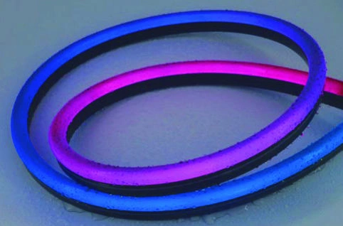
Black-body profiles for addressable color
All three Side Bend all-black configurations are SPI-RGB. Approve both the unlit appearance and the chosen color effects on a sample. The 1023 maximum width is 12.9 mm with a 10 mm base.
| Profile |
Profile size* W × H (mm) | Light / control | LEDs/m |
Cut (mm) |
Power (W/m) |
Output (lm/m) |
Nominal length (m) |
|---|---|---|---|---|---|---|---|
0612 |
6 × 12 |
SPI-RGB |
84 |
71.43 |
14 |
11–120 |
5 |
1023 |
12.9 × 23 |
SPI-RGB |
84 |
71.43 |
14 |
11–66 |
5 |
1220 |
12 × 20 |
SPI-RGB |
84 |
71.43 |
14 |
11–120 |
5 |
24 V DC · IP67 catalog rating. SPI-RGB configurations only. White-light CCT and CRI values do not apply. Confirm the IC and compatible control system.
*Profile size: dimensions follow the catalog cross-section drawings. For three-side 1018/1220, the stated width is the dimensioned body/base width, not the full projecting luminous-cap width. End caps and cable exits add to the finished assembly envelope. Approve the full drawing and mounting sample before machining a recess.
Length and output: nominal length is the catalog supply length, not a universal maximum feed distance. Only the four designated long-run variants carry the 20 m specification. Lumen ranges depend on the selected configuration and operating conditions; confirm the output needed for the project.
MATCH THE LIGHT LINE
Choose the bend plane before the profile size
Side bend describes the permitted curve relative to the emitting face. Mark that face on the installation drawing and check the route against the selected model. Keep the profile within its allowed bend plane; avoid twisting, sharp folds and forced turns.
Signs and outlines
Consider side bend for letters, logos and curved outlines when the route matches the allowed bend plane. Send the tightest corner and the available mounting space for confirmation.
Long architectural contours
Compare the four 20 m variants when feed access and cable routing affect the design. The final supply and wiring need to match the connected length and environment.
Visible decorative lines
Compare standard white-body, three-side and all-black profiles by their lit and unlit sample appearance. Three-side emission describes the luminous surface; it does not mean three-dimensional bending.
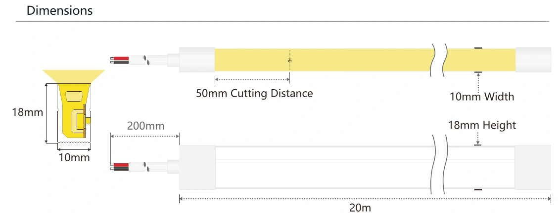
Approve the route and mounting envelope
The catalog does not establish one lamp-body bend radius for this full range. Ask for the exact model’s minimum radius or diameter and the matching hardware. A diameter shown beside a flexible channel must stay with that illustrated accessory and configuration.
Read the Side Bend LED neon flex selection guide, compare Top Bend product configurations or browse the complete LED neon flex range.
BUILD THE COMPLETE ASSEMBLY
Specify end caps, cable exits and mounting together
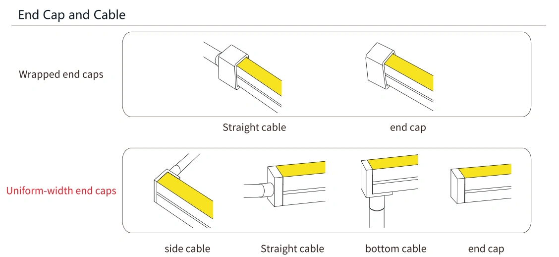
End caps and lead positions
Specify straight, side or bottom cable exit where the chosen model supports it. Wrapped and uniform-width ends have different assembly envelopes. Confirm the end-cap drawing, cable details and finished length in the quotation; options vary by profile.
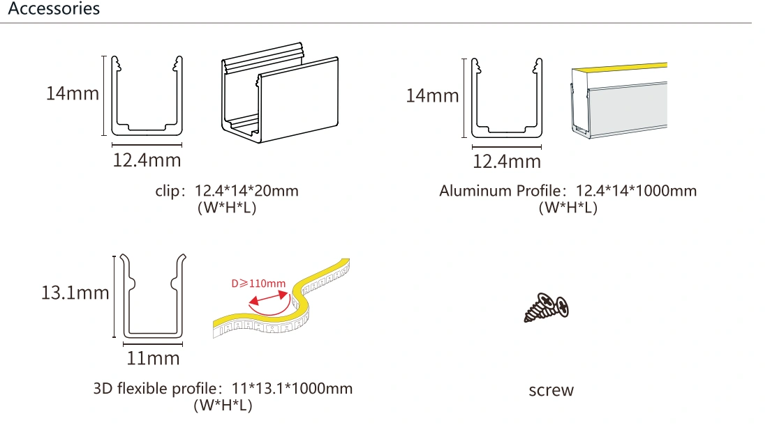
Clips and channels
Match the channel to the actual body and luminous-cap geometry, then check the fit on a sample. The illustrated flexible-channel diameter is an accessory detail, not a universal strip bend radius. Recess dimensions must also allow the approved end caps and lead route.
Agree the cutting and sealing method before the order. Use the LED neon flex installation guide and the dimensional tolerance and channel-fit guide alongside the model-specific drawing.
POWER & CONTROL
Match the 24 V supply to the exact configuration
Fixed-white profiles
Choose one of the listed white CCTs and confirm the required W/m. State any dimming method so the driver and controller can be matched. Separate CCT options do not mean tunable-white operation.
Dedicated 20 m variants
The long-run 0816, 1018, 1020 and 1220 are the configurations listed for 20 m single-end supply. Their internal constant-current design still uses the specified 24 V DC input; do not substitute an arbitrary external constant-current driver.
All-black SPI-RGB
The all-black 0612, 1023 and 1220 require a matched SPI control system. Confirm the IC, addressable sections, controller and wiring. Do not infer pixel count from LEDs/m or assume direct DMX512 compatibility.
Calculate the nominal LED load: selected W/m × connected meters. An 8 W/m long-run configuration over 20 m is 160 W before design allowances. Check driver rating and derating, lead length, conductor size, controller capacity and feed arrangement. Use the specified low-voltage DC supply; do not connect the neon flex directly to AC mains.
Review Mean Well LED power supplies and request a matched system for the installation route and conditions.
SAMPLE TO PRODUCTION
Approve a sample that represents the order
01 / Fit and geometry
Check the full profile width, luminous cap, clip or channel, emitting-face orientation, cable exits and the smallest approved curve. Compare the sample with the recess drawing.
02 / Light and operation
Check the selected white tone or SPI effect, measured power and brightness along the proposed run. Use the intended supply and control equipment during sample approval.
03 / Assembly and records
Record the end caps, sealing, finished lengths and wiring detail. Agree acceptance limits and sample identification so repeat orders can be checked against the approved configuration.
Use the dimension and mounting-fit checklist during sample approval. For project submittals, request documents covering the exact configuration and destination market. Check the document’s model coverage and conditions. Learn more about NPHIS and use the technical document request route.
Order and production
Standard MOQ: USD 1,000 order value. In addition, production with available materials is about 5–7 days, while customized orders take 15–30 days. Confirm sample costs, production timing and shipping scope in the quotation. These estimates do not specify arrival dates.
Commercial warranty
Standard warranty: 3 years. Eligible special or custom configurations may receive up to 5 years under agreed quotation terms. The extended term is configuration-dependent; warranty duration is not a tested operating-life rating.
For other non-standard customizations, please provide detailed specifications—such as specific color temperature (CCT), RGBW, DMX512, 98CRI, 48V voltage, IP68, SDCM <3, or specific dimensions/molding requirements.
PRODUCT DOCUMENTS
Keep the catalog and order drawing together
Our LED Neon Flex Catalog covers this Side Bend range on printed pages 18–36 (PDF pages 21–39). Shortlist a configuration, then request its current profile, end-cap and wiring drawings for the order.
For configuration-specific documents, send a technical document request with the model and destination market.
PRODUCTION & DOCUMENTATION
Equipment and compliance documents
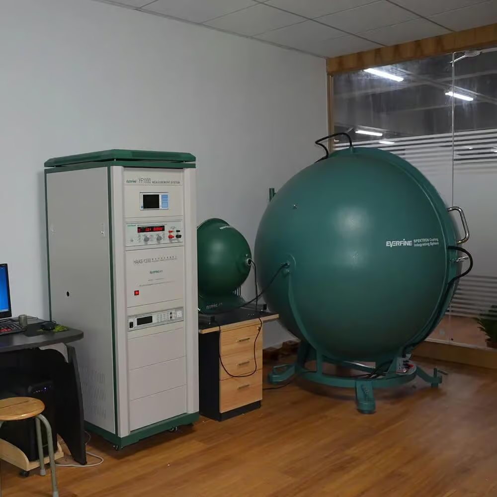
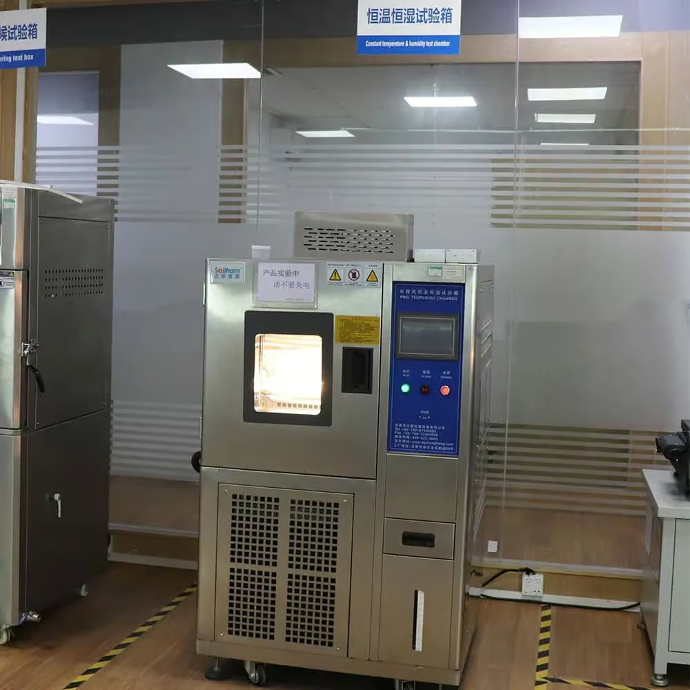
An integrating sphere measures light output and color. The SMT line places LEDs on the circuit board, and the temperature and humidity chamber supports environmental testing. When requesting test data, specify the profile, CCT and operating conditions you want evaluated.
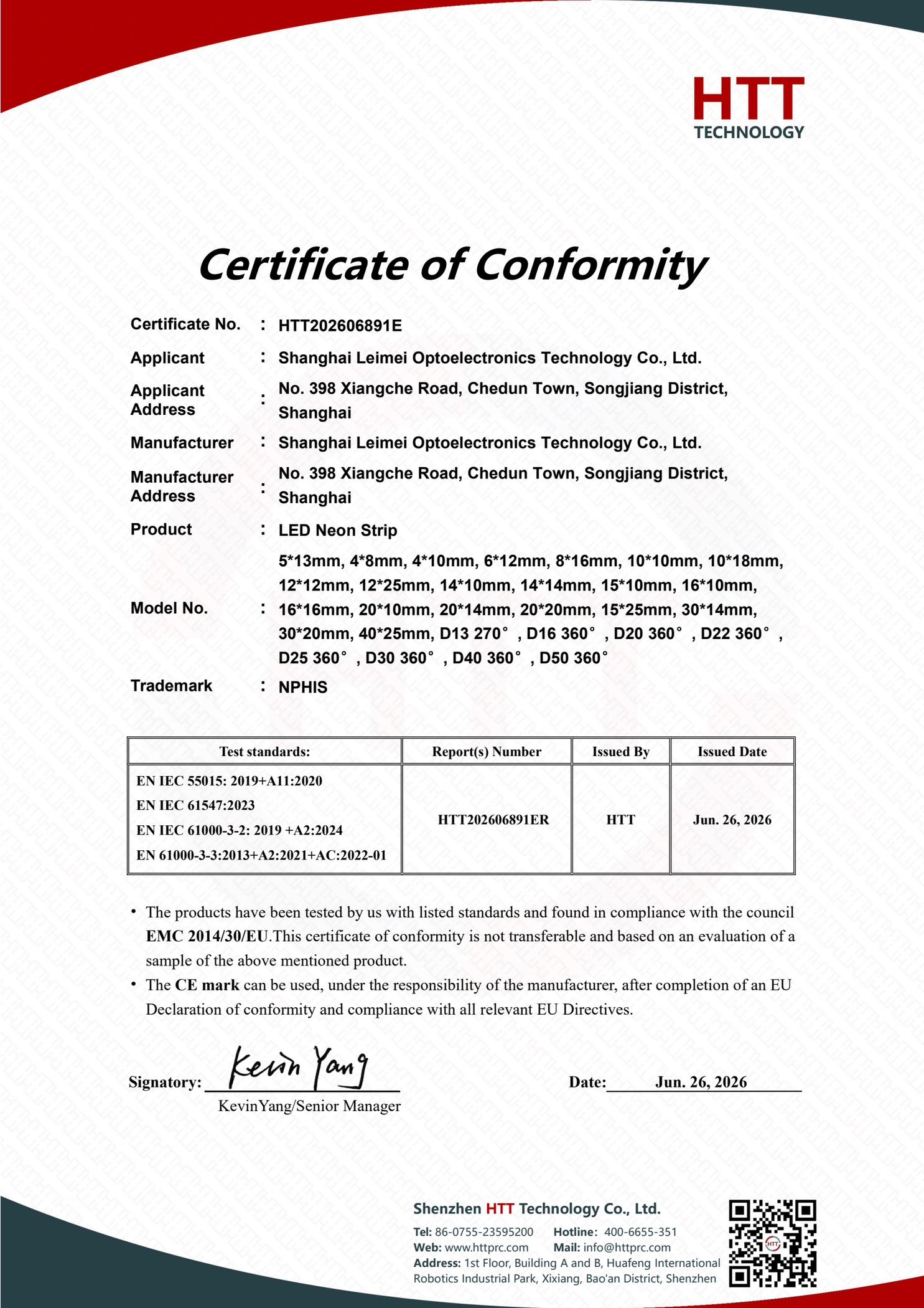
EMC and RoHS documents for NPHIS LED Neon Strip
This document lists Shanghai Leimei Optoelectronics Technology Co., Ltd. as the applicant and manufacturer, and NPHIS as the trademark. The list of model numbers covers all the side bend neon flex strip dimensions shown in the table above. Please provide the ordered configuration and the target market so that we can match the documentation to your purchase.

BUYER QUESTIONS
Side Bend LED Neon Flex FAQs
Direct answers for profile selection, installation planning and wholesale purchasing. Match each answer to the selected catalog variant and agreed order configuration.
Selection and bending
What is side bend LED neon flex?
Side bend LED neon flex combines an LED strip with a flexible silicone diffuser designed to curve in its specified side-bending plane. It creates a continuous-looking light line for outlines, signs and architectural details. This NPHIS catalog range uses 24 V DC. Match the emitting face and bend direction to the installation drawing before choosing the profile size.
What is the difference between side bend and top bend neon flex?
The difference is the permitted bend plane relative to the light-emitting face. A side bend profile and a top bend profile cannot be forced through the same curve in every mounting orientation. Mark the emitting face and route on the drawing, then compare the Side Bend selection guide and Top Bend product configurations. A straight run alone does not determine the bend type.
Which profile size should I choose?
Choose the dimensions that fit the recess, light-line width and mounting hardware. The 0408 is 4 × 8 mm; other models include shaped profiles whose maximum width differs from the model number. For example, 0817 is 10 × 17 mm at its widest point, while 1225 is 15.5 × 25 mm. Check the table notes, end caps and profile-to-channel fit before approving the sample.
What is the minimum bending radius?
There is no single confirmed lamp-body bend radius for all 19 configurations. Request the selected model’s bend drawing with the emitting face and minimum radius or diameter identified. Catalog D values are diameter labels; several appear beside flexible mounting channels and describe that illustrated arrangement. Do not treat an accessory diameter as the strip’s bend radius or transfer it to another model.
Can side bend neon flex form a 90-degree corner?
A 90-degree change in direction needs an approved curve or connection detail, not a sharp fold. Keep the curve within the model’s permitted bend plane and minimum bend dimension. Send the corner drawing, available space and emitting-face orientation for review; a side bend profile does not automatically support twisting or three-dimensional curves.
Can this side bend neon flex replace an existing installation?
A replacement needs to match the existing geometry, electrical system and visual requirements. Compare the full profile dimensions, emitting face, bend direction, cut interval, end caps, cable exits and mounting channel. A shared model number or 24 V rating does not establish interchangeability. Send the existing drawing, product details and installation photos, then approve the proposed replacement on a sample.
Installation, power and control
Can I cut side bend LED neon flex to length?
Yes, at the marked cutting positions for the selected configuration. The 0408 has a 35.71 mm interval; the all-black 0612, 1023 and 1220 SPI-RGB variants have a 71.43 mm interval; the other listed configurations have a 50 mm interval. Final lengths must allow for the chosen end caps and leads. Agree the cutting and resealing method before installation; see the neon flex installation guide.
What power supply do I need?
Use the specified 24 V DC supply and size it for the connected load. Multiply the selected W/m by connected meters, then check driver derating, cable voltage drop, feed arrangement and controller capacity. For example, an 8 W/m configuration over 20 m has a nominal LED load of 160 W before system design allowances. Compare Mean Well power supply options with the proposed installation conditions.
Can one end power a 20 m run?
The four long-run variants—0816, 1018, 1020 and 1220—are cataloged for 20 m single-end supply. This capability belongs to those configurations, not every profile with the same model number. Confirm the supply, lead length, conductor size and installed run. The three-side 1018 and 1220 versions are listed at 5 m and must not inherit the long-run specification.
Is this neon flex waterproof and suitable for outdoor use?
The listed configurations carry an IP67 catalog rating. Outdoor selection must also cover the finished end-cap seal, cable entries, mounting and actual exposure. Cutting or changing connections requires an approved resealing method. Do not treat this page as approval for permanent immersion, pools, saunas or a specific chemical environment; describe those conditions so the configuration and supporting documents can be checked.
Can the white-light profiles be dimmed?
Specify the required dimming method so the 24 V profile, driver and controller can be matched. The white-light catalog lists separate 3000 K, 4000 K and 6500 K options; it does not establish tunable-white operation or universal dimmer compatibility. Confirm the selected control method, wiring and sample performance before ordering.
Do the all-black SPI-RGB models support DMX512?
The catalog identifies the all-black 0612, 1023 and 1220 as SPI-RGB; it does not specify direct DMX512 support. Confirm the IC, compatible controller, addressable sections, wiring and any required interface for the project. LEDs per meter is not a pixel-address count. The white-light CCT and CRI specifications do not apply to these SPI-RGB versions.
Samples, documentation and ordering
What should I check on a sample before a bulk order?
Check the actual profile and channel fit, emitting face, bending route, end caps and cable exits. Then verify the chosen white tone or SPI effect, measured power and brightness along the intended run with the proposed power and control equipment. Record the approved drawing, finished length, sealing arrangement and acceptance limits so the sample represents the production order.
Can I order cut lengths, end caps and mounting accessories together?
Include the required finished lengths, cable exits, end caps, clips and channels in the enquiry so a complete assembly can be quoted. Availability and fit depend on the selected profile and configuration. Approve the connection drawing and sample before production; a nominal reel length does not include every possible end-cap or cable arrangement.
Which drawings and compliance documents should I request?
Request the current profile drawing, wiring detail and documents relevant to the exact configuration and destination market. Check the model coverage and conditions of any certificate or test report. Logos in a general catalog do not identify every covered model. Start with the technical download center and include the required documents in your enquiry.
How long does it last, and what warranty applies?
The standard warranty is 3 years. Eligible special or custom configurations may receive up to 5 years under agreed quotation terms. Warranty duration is not a tested operating-life rating. This catalog does not provide a verified lifetime figure for every listed configuration; operating temperature, power conditions, sealing and installation need to be considered for the project.
What are the minimum order and production lead time?
The standard MOQ is USD 1,000 order value. Production with available materials is typically about 5–7 days; fully customized orders are typically about 15–30 days, depending on quantity and complexity. Confirm the sample cost, production schedule and shipping scope in the quotation. These are production estimates, not arrival-date commitments.
What information is needed for an accurate price quote?
Send the model and variant, quantity, individual finished lengths, white CCT or SPI effect, installation layout, cable exits, power and control requirements, destination and project timing. State whether the quote should include accessories, drivers, controllers, documents and freight. These choices change the supply scope and price. Request a Side Bend project quotation with a drawing or bill of materials.
REQUEST A PROJECT QUOTE
Send your Side Bend neon flex requirements
Tell us the intended light line and the catalog profiles you are considering. Include the following details so the quotation can identify the configuration and complete supply scope.
- Model, variant, quantity and individual finished lengths
- White CCT or SPI-RGB effect and control requirements
- Bending layout, emitting-face orientation and mounting method
- Indoor/outdoor conditions, cable exits and feed locations
- Destination, required documents and project timing
For a separate enquiry, open the project quotation page. For contact details, visit Contact NPHIS.
BUYER & INSTALLER GUIDES