
In a recent outdoor-outline project review, the main question was not whether silicone neon flex could follow the shape. It was whether 12V vs 24V LED neon flex would keep the final section as bright as the first while keeping power-supply locations and cable routes practical. From our factory’s perspective, this decision comes down to four engineering issues: cut precision, operating current, voltage drop, and power-zone planning.
The voltage printed on a quotation is only the starting point. We also need the exact profile, wattage per metre, colour configuration, feed direction, cable length, and installation temperature before confirming a workable maximum run.
| Project condition | Starting choice | Must verify before order |
|---|---|---|
| Short letters, tight curves | 12V may fit | Cut unit, bend direction, actual W/m |
| Longer static linear runs | 24V is usually the starting point | Single/dual-end feed limit for the exact model |
| Facade, bridge, RGBW high-load | 24V plus a power-zone plan | Voltage-drop calculation, injection points, service access |
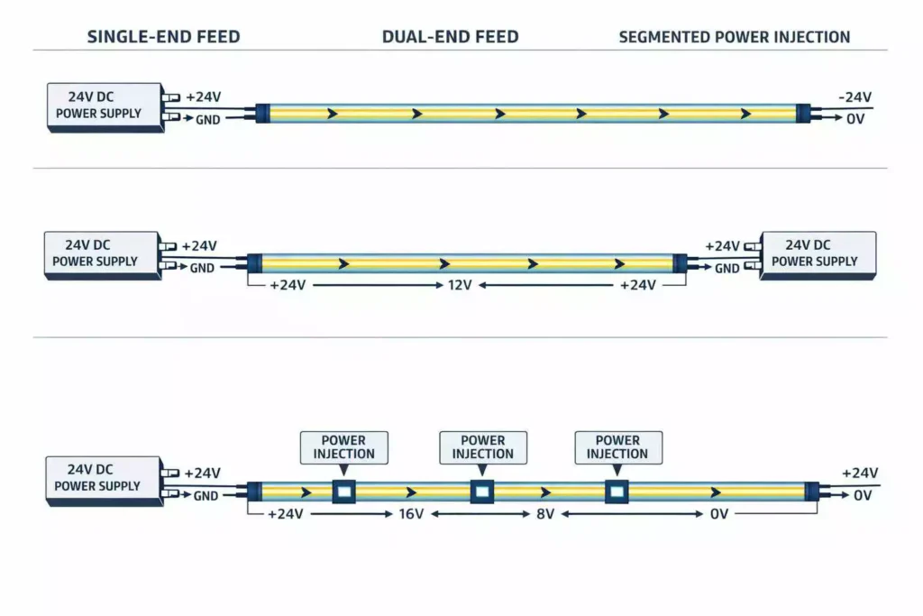
Table of Contents
12V vs 24V LED Neon Flex: The Decision in One Table
| Selection factor | 12V | 24V | Engineering implication |
|---|---|---|---|
| Same-load current | Higher | Approximately half the 12V current | 24V normally reduces feeder current for the same wattage. |
| Voltage-drop sensitivity | Higher percentage drop for the same lost voltage | Lower percentage drop for the same lost voltage | 24V usually maintains brightness and colour consistency over a longer circuit. |
| Cut length | Often shorter and more precise | Often longer, depending on circuit design | Check the actual cut unit in millimetres, not voltage alone. |
| Power-zone count | More zones may be required on long runs | Fewer zones may be possible | The final count depends on W/m, cable resistance, feed method, and permitted dimming. |
| Best fit | Letters, logos, short shapes, compact accents | Facades, retail perimeters, hospitality coves, longer linear features | Select the complete electrical system rather than voltage in isolation. |
For the same electrical load, raising the operating voltage reduces the current:
For example, a 120 W load draws 10 A at 12V but only 5 A at 24V. That difference affects cable size, connector loading, controller capacity, fuse selection, and the number of feed points.
Cable power loss increases with:
Therefore, halving current can substantially reduce resistive cable loss when the conductor resistance remains unchanged. This does not mean that every 24V neon flex can run twice as far. Internal PCB resistance, LED grouping, wattage, colour, and thermal conditions remain product-specific.
Voltage Drop Is a System Issue, Not a Reel-Length Claim
Voltage drop occurs throughout the complete circuit. It can develop in the neon flex PCB, extension cable, connectors, solder joints, controller terminals, and distribution equipment.
That is why statements such as “maximum 5 metres” or “maximum 10 metres” are only preliminary selection guidelines. They are not universal installation guarantees.
The usable run changes according to:
- Actual product wattage per metre
- PCB copper weight and conductor width
- Monochrome, RGB, RGBW, or pixel configuration
- White-channel operating current
- Single-end or dual-end power feed
- Cable gauge and feeder length
- Connector and joint resistance
- Ambient and enclosed-space temperature
- Acceptable brightness difference at the run end
A 10-metre reel does not automatically mean that all 10 metres should be powered from one end. Reel length is frequently a packaging specification, while feed length is an electrical specification.
The voltage arriving at the neon flex should also be measured under full load. An unloaded 24V reading at the power supply does not show what reaches the last illuminated segment after the cable and product losses have been applied.
For dual-end feeds and injected power zones, polarity must remain consistent. Circuits must also be fused and distributed according to the approved design. Separate power supplies should not be paralleled on the same continuous conductors unless the power architecture is specifically engineered for that arrangement.
Choose 12V When Cut Precision Matters More Than Run Length
2V neon flex is not a lower-quality product. It is often selected because its circuit topology can support shorter cut units.
However, voltage alone does not guarantee a particular cut length. LED count, series grouping, resistor layout, PCB design, and optical pitch determine the real cutting interval.
Short-Cut Lettering and Logos
Small letters and detailed logos may contain many short straight sections. A long cut unit can leave dark gaps at corners or force installers to alter the original artwork.
For these applications, we review:
- The shortest line in the drawing
- Cut-point positions around each letter
- Cable exits between separate sections
- Dark-zone risk at end caps and connectors
- The minimum permitted bend radius
The buyer should provide vector artwork or dimensioned drawings. A photograph without scale is not sufficient for cut planning.
Compact Indoor Accents
12V can work well for display features, small counters, decorative wall shapes, and short cabinet accents. These projects usually have limited individual lengths and relatively short feeder cables.
The power supply must still be accessible and correctly sized. Placing an oversized driver inside a sealed, unventilated cavity can create a separate thermal-reliability problem.
Reducing Offcut Waste
Cut-unit length affects material yield. If a shape requires 230 mm but the product can only be cut every 100 mm, the practical section may need to be 200 mm or 300 mm. Across hundreds of letters, this can create significant waste or visible design changes.
Before approving a 12V model, confirm:
- Cut marks: Request the cut interval in millimetres and a marked PCB drawing.
- Minimum bend radius: Verify both the specified radius and the direction of bending.
- Connector exit direction: Confirm front, side, or bottom cable exit against the mounting channel and site access.
- End treatment: Include end-cap length and dark-zone allowance in the drawing.
- Wattage tolerance: Use the confirmed production value for PSU and cable calculations.
Choose 24V for Longer Commercial Linear Runs
We normally start with 24V for facades, retail perimeters, hospitality coves, corridor outlines, and other commercial linear applications. For the same load, the lower current simplifies feeder planning and reduces stress on cables, connectors, and controller outputs.
This is particularly useful when the power supply cannot be installed immediately beside the first section. A long low-voltage feeder still needs to be calculated, but 24V generally gives the engineer more practical options.
Typical 24V applications include:
- Long static-white architectural outlines
- Retail ceiling and wall perimeters
- Hotel lobby and corridor coves
- Exterior landscape features
- Bridges and public-space outlines
- RGBW or addressable colour-changing installations
For controlled installations, buyers can review our 24V DMX512 RGBW neon flex for dynamic commercial projects. Pixel pitch, DMX addressing, decoder capacity, data topology, and power injection must all be coordinated before production.
A 24V product does not eliminate power injection. Long runs can still develop visible dimming, white-point shift, or colour inconsistency.
RGBW loads need particular attention. A scene using only one colour may pass a site test, while full-output RGBW can expose inadequate cables or overloaded controllers. We therefore calculate and test using the defined worst-case scene, not only the normal programmed effect.
Please refer to our article:DMX LED RGBW neon flex for facade and entertainment lighting
Size the Power Supply and Plan the Feed Points
For preliminary PSU sizing, we use:
Dividing by 0.80 provides approximately 20% operating headroom. For example, 20 metres of 10 W/m neon flex creates a nominal 200 W load:
The headroom helps prevent continuous operation at the driver’s maximum nameplate rating. It also provides allowance for normal product tolerance and operating conditions.
However, headroom is not permission to ignore thermal derating. PSU output can be reduced by high ambient temperature, poor ventilation, enclosure design, or manufacturer-specific derating curves.
Power supplies should be divided into maintainable zones rather than concentrated into one large circuit without service planning. Each zone should remain within the capacity of its PSU, controller, connector, fuse, and feeder cable.
Before Issuing a PO, Confirm:
- Maximum single-end feed length for the exact model and colour
- Maximum dual-end feed length and approved wiring method
- Power-injection spacing
- Cable conductor size and total feeder length
- Connector and extension-cable current ratings
- Full-load scenarios, especially RGBW full output
- PSU load percentage and thermal derating
- Controller or decoder current per channel
- Fuse protection for each distribution branch
- Voltage available at the first and last powered sections
- Outdoor PSU location, drainage, ventilation, and maintenance access
- Access to connectors and injection points after installation
Factory Verification: What Should Be Tested Before Production?
We recommend approving test evidence for the exact ordered model. A report for another profile, wattage, PCB, or LED configuration may not represent the product being purchased.
| Buyer question | Evidence to request | Selection impact |
|---|---|---|
| Will the end dim? | Exact-model voltage-drop test | Determines feed length, dual-feed suitability, and injection spacing. |
| Is batch brightness consistent? | Integrating-sphere record | Confirms lumen output, power, CCT, CRI, and batch consistency. |
| Is it stable in outdoor heat/cold? | Temperature-cycle record | Supports profile, material, cable, and installation-temperature selection. |
| Does bulk match the sample? | Aging record and pre-shipment sample comparison | Helps verify production stability before packing and shipment. |
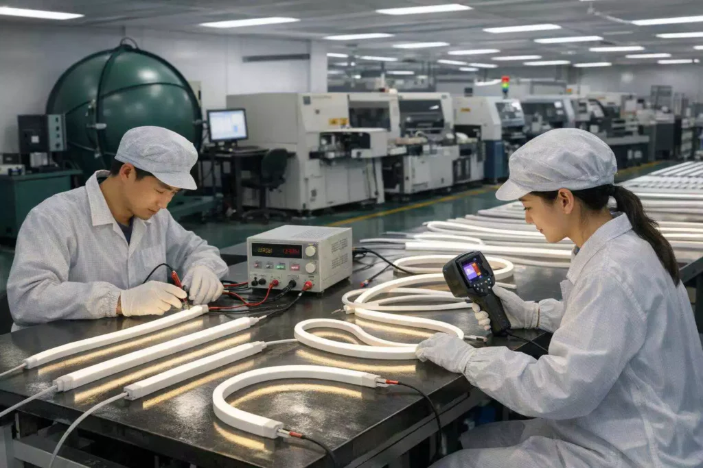
At our factory, the voltage-drop test should reproduce the intended configuration. This means using the correct length, input voltage, feed direction, and operating mode.
For a tunable or RGBW model, testing only a low-load colour is insufficient. We record input power and compare the beginning and end of the run under the agreed full-load condition.
Buyers can also ask for:
- Beginning-, middle-, and end-point voltage readings
- Illuminance or luminance comparison along the run
- Thermal images after stabilization
- CCT and colour-coordinate records
- Cable and connector temperature observations
- A production-sample aging report
- Photos showing the test length and feed method
EU Project Documentation Check — Do Not Treat Voltage as Compliance
Choosing 12V or 24V does not automatically make neon flex compliant for an EU project. Voltage is an electrical design parameter; compliance depends on the product configuration, intended use, supplied control gear, documentation, and the economic operator’s role.
EU Ecodesign requirements address energy-related performance and product information for in-scope light sources and separate control gears. The primary framework includes Commission Regulation (EU) 2019/2020. RoHS addresses restricted hazardous substances in electrical and electronic equipment; the European Commission’s RoHS guidance should be checked for current requirements and exemptions. These are different obligations, so a RoHS report does not prove Ecodesign conformity.
Before ordering, identify whether the neon flex is supplied as a light source, part of a containing product, or within a project-specific assembly. Confirm the applicable standards, test reports, labels, technical file, and Declaration of Conformity for the exact SKU. EU importers should also verify their own traceability, documentation-retention, labelling, and market-surveillance responsibilities. Project specifications may impose additional EMC, electrical-safety, IP, fire-performance, or building-code requirements.
Send Your Drawing for a Voltage and Power Plan
A useful RFQ needs more than total metres and a requested price. Send our engineering team the following details:
- Application type: facade, signage, cove, bridge, retail, or hospitality
- Dimensioned drawing, preferably PDF, DWG, DXF, or AI
- Individual section lengths rather than only total project length
- Required silicone profile and bending direction
- Light colour, CCT, RGB, RGBW, or addressable control requirement
- Target wattage per metre and required brightness
- Indoor or outdoor installation
- Ambient temperature and any enclosed mounting conditions
- Distance from the power room to each lighting zone
- Available cable routes and maintenance points
- Required connector exit direction
- Control protocol and planned controller
- Installation country and required compliance documents
- Sample approval and project delivery schedule
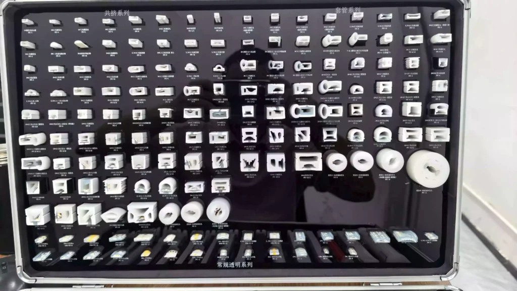
If the profile has not yet been finalized, buyers can compare silicone neon flex profiles and voltage options before requesting samples. For architectural planning considerations, our guide to silicone neon flex for architectural lighting also explains profile, bending, mounting, and specification factors.
Our project process is:
Drawing → Engineering Review → Sample → Power/Voltage-Drop Check → Bulk Production
During the engineering review, we divide the drawing into manufacturable sections. We then check cut points, bend direction, cable exits, feed distances, PSU capacity, controller loading, and service access. The resulting quotation can therefore identify the proposed voltage and power zones instead of leaving those decisions until installation.
Please refer to our article: Silicone Neon Flex for Architectural Lighting.
Conclusion — Choose the System, Not Just the Voltage
Choose 12V when short, precise cuts are more important than long feed lengths. Choose 24V as the starting point for commercial linear runs, but do not treat it as a substitute for cable calculations and power-injection planning. Always verify maximum lengths using test records for the exact neon flex model, wattage, colour, and feed configuration.
FAQs
❓️ Is 24V LED neon flex always brighter than 12V?
No. Voltage alone does not determine brightness. Brightness depends on LED efficiency, LED density, drive current, silicone optical transmission, profile size, and actual wattage per metre. A properly designed 12V model can be as bright as a 24V model. The main advantage of 24V is lower current for the same power, which usually makes voltage-drop and feeder-cable planning easier.
❓️ Can 24V LED neon flex run for 10 metres from one end?
It depends on the exact product. A 10-metre reel is not proof that the full reel can be powered from one end. We need to verify the profile, W/m, LED circuit, PCB resistance, colour, cable length, and permitted end-to-start brightness difference. Ask for an exact-model voltage-drop test before using a 10-metre single-end feed in a commercial project.
❓️ Does 12V LED neon flex have a shorter cutting length?
Often, but not always. The cutting interval is determined by the LED grouping and PCB circuit design. For letters and logos, request the cut unit in millimetres. We also recommend placing the cut points over the actual drawing before approving a sample.
❓️ How often should power be injected into LED neon flex?
There is no universal injection interval. Injection spacing depends on voltage, wattage per metre, product resistance, feeder cable, colour mode, and the acceptable voltage at the end of each zone. For RGBW or addressable products, the calculation should use the maximum intended load. A low-power animation does not represent the worst-case electrical condition.
❓️ Can we connect both ends of LED neon flex to one power supply?
A dual-end feed may be used when the exact product and wiring plan permit it. Both connections must have the correct polarity and adequate conductor size. The installation should follow the approved circuit drawing. Do not connect unrelated power-supply outputs to the same continuous circuit without a properly engineered power-distribution design.
❓️ What power-supply headroom should we use?
For many commercial LED projects, we begin with approximately 20% headroom. This means the nominal lighting load should normally remain at or below about 80% of the selected PSU capacity. The PSU manufacturer’s thermal derating curve still applies. Higher ambient temperatures or sealed enclosures may require additional derating.
❓️ Why does RGBW neon flex show colour variation near the end?
RGBW neon flex has multiple channels and can draw high current when several channels operate together. If voltage falls along the run, the channels may not lose output uniformly. This can produce lower brightness or a visible colour shift near the end. Correct cable sizing, shorter power zones, and planned injection points are the usual solutions.
❓️ Should voltage drop be calculated in the extension cable and neon flex?
Yes. Both parts matter. The extension cable causes voltage loss before power reaches the product, while the internal conductors cause additional loss along the neon flex. Connectors, solder joints, controllers, and distribution terminals also add resistance. A reliable calculation and test must consider the complete circuit.
❓️ Is 24V LED neon flex automatically compliant for EU projects?
No. Operating voltage does not prove RoHS, Ecodesign, EMC, electrical-safety, or other project compliance. Buyers should request documentation for the exact product configuration. EU importers must also check their own labelling, traceability, documentation, and market-surveillance responsibilities.
❓️ What should we send NPHIS before requesting a quotation?
Send a dimensioned drawing, individual section lengths, required profile, bending direction, colour, W/m, voltage preference, indoor or outdoor conditions, cable distances, PSU locations, control protocol, installation country, and required compliance documents. With this information, our factory can review cut points, power zones, cable exits, controller loading, sample requirements, and voltage-drop risks before bulk production.
Can’t find the asnwer you are looking for?
Write us a questionand we will be happy to answer it