
When a buyer asks us for “50 meters of neon with a chasing effect,” our first question is never the price per meter.
Instead, we ask a harder question: can those 50 meters still produce the intended animation reliably after they are divided across walls, letters, floors, or façade sections?
Here is the core difference. A standard RGB neon flex changes the whole connected run as one color zone. Addressable LED neon flex, however, divides the line into controllable pixels. Each pixel can show a different color and brightness at the same time. That is what makes chasing, flowing, gradient, mapped, and interactive effects possible.
But be careful. Adding addressable ICs does not automatically create a reliable pixel lighting system.
The effect, pixel pitch, protocol, controller, power distribution, data direction, connectors, physical profile, and maintenance plan must be engineered together. Otherwise, a sample may work perfectly on our factory bench — yet fail after the installer spreads it across the actual building.
Based on our years of LED neon flex manufacturing at NPHIS, this guide shows importers, contractors, system integrators, and lighting brands how to move from a creative concept to a testable sample, a factory acceptance test (FAT), and a controlled bulk order.
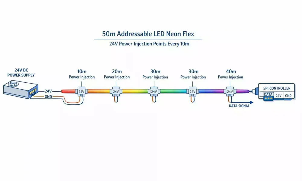
Table of Contents
Addressable LED Neon Flex: 60-Second Buyer Definition
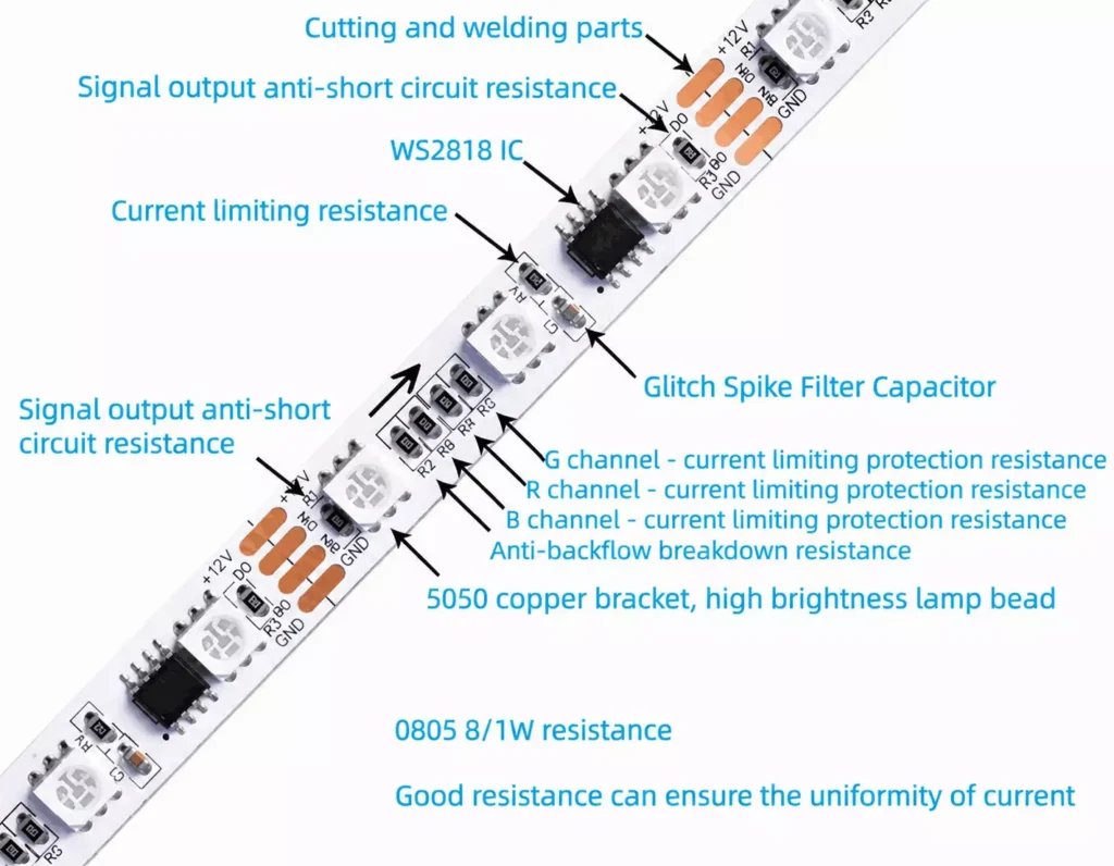
Addressable LED neon flex combines a diffused flexible silicone profile with LEDs and digital control ICs.
Each controllable section is called a pixel. A pixel may contain one LED or a group of LEDs, depending on the product.
That distinction matters more than most buyers realize.
For example, “60 LEDs per meter” does not always mean “60 pixels per meter.” If six LEDs share one IC, the product only has ten controllable pixels per meter.
Addressable neon can create:
- Chasing and flowing effects
- Moving gradients
- Sequential brand animations
- Multi-zone color control
- Music-synchronized scenes
- Pixel-mapped patterns
- Sensor-triggered interactive lighting
Therefore, confirm these five definitions before comparing any prices:
| Term | What the Buyer Must Confirm |
|---|---|
| LED density | Physical LEDs per meter |
| Pixel density | Independently controllable sections per meter |
| Pixel pitch | Distance between controllable pixels |
| Cutting unit | Smallest section that can be physically cut |
| Channel format | RGB, RGBW or another supported configuration |
Remember: the lowest price per meter is not the lowest project cost. The wrong pixel pitch, protocol, or cutting unit can increase controller quantity, programming work, cable runs, and installation waste.
Start With the Effect, Not Reel Length
Total length is needed for a quotation. However, length alone does not explain what the system must do.
A useful project brief starts with the intended effect:
- Should the animation move from left to right?
- Should it follow the outline clockwise?
- Must separate sections run the same effect simultaneously?
- Is the content a simple chase or mapped video?
- Does it react to music, occupancy, or another sensor?
- Will it run from a lighting console?
- Does it need standalone scheduled playback?
- Is clean architectural white also required?
Consider two 50-meter projects. The first is a retail ceiling that plays a slow repeating gradient. The second is a set of irregular lines that respond to music in real time.
Same length. Completely different pixel density, controller, programming, and data-distribution needs.
So, before selecting a product, create a simple effect schedule:
| Scene | Visual Behavior | Trigger | Playback Method |
|---|---|---|---|
| Daily mode | Static brand colors | Schedule | Standalone controller |
| Welcome mode | Movement toward entrance | Sensor or command | Interactive input |
| Event mode | Synchronized multi-zone animation | Operator | Console or media server |
| Closing mode | Slow dimming sequence | Schedule | Standalone controller |
This helps the factory understand the commercial purpose of the installation — not just its electrical load.
Pixel Pitch: How It Changes Animation and the BOM
Pixel pitch controls the visual resolution of the illuminated line.
A shorter pitch gives more controllable points per meter. This produces smoother gradients and finer motion. However, it also increases the total pixel count, controller capacity, mapping complexity, programming time, and cost.
A longer pitch reduces controllable points. It suits large outlines viewed from a distance. But at close range, motion may look visibly segmented.
| Project Type | Pixel-Design Priority |
|---|---|
| Close-view retail feature | Smooth movement, less visible segmentation |
| Animated signage | Accurate motion around letters and corners |
| Hotel / restaurant feature | Balanced resolution, simple scene control |
| Stage installation | Response speed and synchronization |
| Interactive sculpture | Flexible mapping, real-time control |
| Large building outline | Visibility, reliability, manageable scale |
Before quoting, ask the supplier to confirm: LEDs per meter, pixels per meter, LEDs per pixel, pixel pitch, cutting unit, RGB/RGBW format, IC model, data direction, controller compatibility, pixels per output, and the recommended section length.
SPI vs DMX512: Which Architecture Fits Your Project?
Both SPI and DMX512 products can create addressable effects. Neither protocol is automatically right for every project.
The decision should be based on your system architecture:
| Decision Factor | SPI Addressable Neon | DMX512 Addressable Neon |
|---|---|---|
| Control source | Compatible pixel controller | DMX controller, console or gateway |
| IC compatibility | Controller must support the selected IC | Addressing and channel mode must match |
| Data distribution | Nearby pixel outputs or converters | Integrates with professional DMX/network infrastructure |
| Pixel density | Supports detailed pixel configurations | Depends on product and addressing design |
| Commissioning | IC setting, pixel order, direction must match | Address, channel order, universe must match |
| Failure behavior | Depends on single/backup-data architecture | Depends on IC and parallel/serial architecture |
| Typical priority | Flexible pixel effects, controller choice | Professional lighting-system integration |
Do not rely on oversimplified rules such as:
- “SPI is only for small projects.”
- “DMX can always run hundreds of meters.”
- “One failed DMX pixel can never affect another.”
- “Any SPI controller can control any SPI product.”
In reality, controller capacity, data distance, and failure behavior are model-specific. The DMX512 protocol itself is defined by the ANSI E1.11 standard maintained by ESTA — but how each product implements it varies.
For project-specific advice, send us your controller model, software, pixel quantity, cable distance, and layout.
For more detail, see our DMX LED Neon Flex for Façade & Entertainment Lighting guide and the DMX512 RGBW Silicone LED Neon Flex product page.
Buyer Concern → NPHIS Engineering Solution
A professional supplier converts buyer concerns into engineering decisions. Here is how we do it at NPHIS:
| Buyer Concern | Engineering Response |
|---|---|
| Will a 50-meter effect run continuously? | Divide into calculated power and data zones — never one uncontrolled electrical run |
| Will the animation run backward? | Mark input, output and data direction on pixel map, labels and drawing |
| Will outdoor joints leak? | Define factory-cut sections, cable outlets, connector type, sealing method, field-joint policy |
| What if one pixel fails? | Confirm IC transmission architecture; demonstrate failure behavior during sample testing |
| SPI or DMX512? | Compare controller, pixel count, signal distribution, software and maintenance |
| Cut sections to my drawing? | Create a section schedule that respects the product's cutting unit |
| How to replace a failed section? | Define connector access, section boundaries and spare parts before installation |
| Match my existing controller? | Verify protocol, IC, color order, output capacity and electrical interface |
| Approve before 500 meters? | Representative prototype + documented Factory Acceptance Test (FAT) |
| Repeat orders match batch 1? | Record the approved configuration and production controls |
Do you have any other questions for us?
Feel free to reach out for further inquiries or information.
Three Problems That Cause Most Pixel-Neon Project Failures
Many failures blamed on “bad neon” actually begin before installation. Three areas deserve special attention.
1. Voltage Drop and Power Distribution
Voltage drop happens when current travels through conductors with resistance. As distance and current increase, the voltage at the far end decreases.
Typical symptoms:
- Reduced brightness and color shift
- Inconsistent white
- Flicker under high-output scenes
- Unstable pixels
- Overloaded connectors or cables
Important: a larger power supply alone does not fix voltage drop along an undersized conductor.
The correct engineering process:
- Confirm the product’s verified power consumption
- Record every section length
- Calculate the load per power zone
- Select conductor size and cable route
- Calculate voltage drop
- Define power-injection points
- Keep the PSU within a safe loading margin
- Measure voltage under a demanding test scene
A 50-meter visual effect may look continuous. Electrically, however, it must be divided into controlled sections.
Also, beware of universal claims like “inject power every 10 meters.” The correct interval depends on voltage, watts per meter, wire size, connector rating, and allowable voltage variation. For the full calculation method, see our Long Run LED Strip Voltage Drop guide.
2. Signal, Addressing and Data-Direction Problems
Signal problems often look like product defects:
- Random flashing or frozen pixels
- Incorrect colors or reversed animation
- The first section working while later sections fail
- Effects losing sync after restart
Common causes include: wrong IC selected in the controller, incorrect RGB/RGBW channel order, data connected backward, excessive device distance, poor grounding, interference, wrong addressing, exceeded output capacity, or a pixel map that does not match the installed layout.
The solution is a documented signal plan — not trial and error on site. The drawing should show: controller location, output number, data direction, section start/end, pixel range, address or universe, converters, cable route, power zone, and maintenance access.
3. Waterproofing, Connectors and Field Joints
An IP rating on the product body does not prove the installed system is protected. IP ratings follow the IEC 60529 standard, and the rating only applies to the assembly that was actually tested.
Outdoor reliability also depends on: cable-entry construction, end caps, connectors, factory and field joints, installation orientation, drainage, mechanical stress, correct sealant curing, and installer workmanship.
For permanent outdoor projects, decide before production whether sections will be:
- Cut and sealed at the factory
- Connected with project-specific waterproof connectors
- Joined on site under a documented process
- Supplied with pre-assembled spare sections
Ask your supplier exactly which assembly the IP evidence covers. A report for the neon body may not cover every customized connector or field joint.
Controller Architecture and Pixel Mapping
The controller does not simply “make the neon change color.” It translates content into instructions for defined pixels.
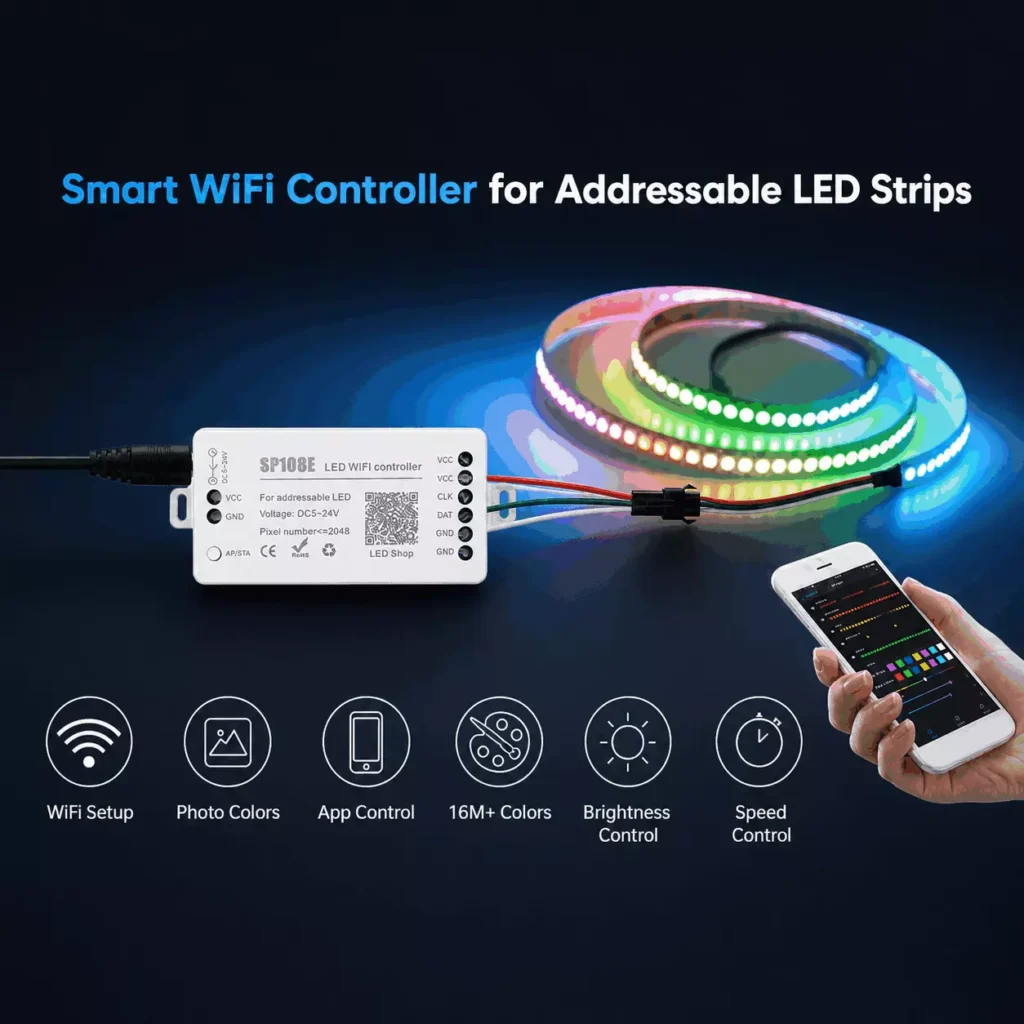
Before choosing a controller, confirm: supported IC or DMX mode, RGB/RGBW channel order, pixels per output, total pixel capacity, number of outputs, network input, standalone playback, real-time input, software compatibility, synchronization, restart behavior, and remote management.
A pixel map connects the digital content to the physical installation. For each neon section, record:
| Field | Purpose |
|---|---|
| Section ID | Matches drawing, product label and packaging |
| Start / end point | Defines physical orientation |
| Data direction | Prevents reversed effects |
| Section length | Supports production and installation |
| Pixel quantity | Supports controller allocation |
| Pixel range | Connects physical line to content |
| Controller output | Identifies the signal source |
| Power zone | Identifies the electrical supply |
| Connector location | Supports installation and maintenance |
Crucially, the factory, programmer, and installer must all use the same revision of this document.
Power Distribution and Signal Distribution
Plan power and data as two related but separate systems:
| Power-Distribution Questions | Signal-Distribution Questions |
|---|---|
| What is the verified load per section? | Which protocol and IC are used? |
| Where are the power supplies located? | Where is the controller located? |
| What conductor size is required? | How far is the first pixel from the controller? |
| Where is power injected? | Is a gateway, repeater or converter required? |
| What is the voltage at the far end? | What is the data direction? |
| Are connectors within current limits? | How are pixels and outputs mapped? |
| Can a PSU be replaced after installation? | What happens after signal loss or restart? |
The finished engineering package should include both diagrams.
Choose the Physical Neon Profile
The correct control system cannot compensate for the wrong physical profile.
Confirm: bending direction (top-bend, side-bend, 3D or round), cross-section dimensions, minimum bending radius, cutting unit, cable outlet direction, connector dimensions, mounting channel, joint visibility, maximum factory-assembled length, indoor/outdoor use, maintenance access, and spare-section strategy.
Some quick rules:
- For signage, the cutting unit must fit the letter geometry.
- For curved architecture, the bending direction must match the drawing.
- For suspended installations, the viewing angle and visible back surface matter.
Browse the available profiles in our Silicone LED Neon Flex collection. Always confirm final dimensions against the selected product’s current datasheet.
Prototype Before Bulk Production
A valid prototype must reproduce the project’s most difficult condition. A short piece running only a factory demo mode proves nothing about a large installation.
The prototype should use: the proposed neon model, proposed pixel pitch, final (or equivalent) controller, representative cable distance, intended connectors, actual animation, realistic section geometry, and the proposed mounting and outdoor assembly.
The prototype should answer:
- Is the animation smooth enough at the viewing distance?
- Is the direction correct?
- Are pixels visible through the diffuser?
- Is the channel order correct?
- Does the controller restart correctly?
- Do multiple sections stay synchronized?
- Can a section be disconnected and replaced?
- Does the sealing process match the installation?
Then approve the sample in writing. Record the product code, IC, pixel pitch, profile, color format, cable outlet, connector, and controller settings.
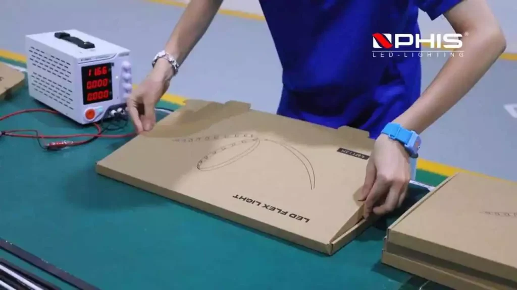
Factory Acceptance Test (FAT)
Before bulk shipment, the FAT verifies the agreed configuration and system behavior.
Product checks
Profile and dimensions, bending direction, section lengths, cable outlets, connectors, data-direction labels, surface appearance, continuous illumination, joint appearance, and packaging by installation zone.
Electrical and control checks
Input voltage, operating current under the agreed test condition, voltage at defined points, pixel order, RGB/RGBW channel order, addressing, animation direction, output synchronization, restart behavior, response after signal loss, approved scene files, and camera-flicker checks where required.
Outdoor assembly checks
End-cap and cable-entry inspection, connector assembly, curing records, ingress testing per the project specification, and identification of field joints excluded from factory testing.
Handover documents
Pixel map, section schedule, controller-output schedule, address schedule, wiring diagram, power-distribution diagram, datasheets, approved effect file, section labels, spare-parts list, installation notes, and the FAT record.
At NPHIS, every batch is tested and thermally aged before shipment, with color consistency held to SDCM < 3. Exact measured values are always more persuasive than a generic “100% tested” claim.
Application Decision Matrix
| Application | Main Priority | Key Buyer Question |
|---|---|---|
| Animated signage | Sectioning and direction around letters | How will the animation continue between separate letters? |
| Retail display | Close-view smoothness, simple operation | Can store staff change scenes without reprogramming? |
| Hospitality feature | Ambience, white quality, event scenes | Is RGBW required for usable white light? |
| Stage and event | Synchronization, fast replacement | Can damaged sections be exchanged between shows? |
| Building outline | Distribution and maintenance access | Where will controllers and PSUs be serviced? |
| Media façade | Mapping, network scale, content workflow | Who creates and approves the pixel map? |
| Interactive installation | Input compatibility and latency | Which sensor or software triggers the effect? |
| Sculpture | Geometry, viewing angle, custom sections | How does the physical curve match the digital map? |
What a Professional Supplier Should Ask Before Quoting
A reliable engineering discussion includes questions from the supplier. If the only questions are “How many meters?” and “What voltage?”, important risks stay unresolved.
A professional supplier should ask:
- What is the application, and what should the animation do?
- What is the viewing distance?
- How many physical sections are on the drawing, and how long is each?
- Is RGB or RGBW required?
- Is a controller already selected? Which software or console will run it?
- How far is the controller from the first pixel?
- Where can power supplies and gateways be installed?
- Indoor or outdoor? Sections cut and sealed at the factory?
- How will damaged sections be accessed?
- Quantity, prototype requirements, and destination-market certifications?
Equally important: the supplier should openly say what cannot be confirmed until a drawing or sample exists. That honesty is more trustworthy than saying “yes” to everything.
Addressable Neon Flex RFQ Checklist
Send the following for an engineering review:
Project details — company and country; your role (buyer / contractor / integrator); application; indoor or outdoor; installation drawing; delivery date; sample requirement; estimated quantity.
Lighting effect — static and animated scenes; movement direction; RGB or RGBW; pixel-density or viewing-distance requirement; synchronization; interactive or music input; standalone or live control.
Physical sections — total length; length of each section; bend direction; profile-size restriction; cable outlet; connector preference; mounting method; required spares.
Control system — SPI or DMX512 preference; existing controller model; software or console; pixel map if available; controller-to-neon distance; network infrastructure; restart and monitoring needs.
Commercial requirements — trial and bulk quantity; packaging; private label; destination market; certificates or reports; delivery schedule.
FAQs
❓️ Will 50 meters of addressable neon work as one continuous animation?
Yes, the visual effect can flow across 50 meters. However, the project must not be treated as one uncontrolled power and data run. It normally needs defined sections, power zones, controller outputs, and mapped pixel ranges.
❓️ How do I prevent the animation from running backward?
Mark the data direction and start point on the drawing, pixel map, product label, and packaging. Then verify the direction during the prototype and the FAT.
❓️ What happens if one pixel fails?
It depends on the IC and transmission architecture. Single-data, backup-data, and parallel-transmission products behave differently. Ask the supplier to demonstrate the failure behavior of the selected model.
❓️ Can NPHIS cut sections according to my drawing?
Yes, subject to the product’s cutting unit and the required sealing and connector method. Send a section schedule with every length and cable direction for engineering review.
❓️ Can the neon match my existing controller?
Compatibility requires more than matching “SPI” or “DMX.” Send the controller model, supported ICs, output capacity, electrical interface, software, and pixel count for verification.
❓️ Should I choose SPI or DMX512?
Choose based on the project architecture: controller, pixel count, signal distribution, software, maintenance plan, and existing lighting infrastructure — not on price alone.
❓️ Can outdoor joints be truly waterproof?
Outdoor reliability depends on the complete assembly — cable entry, end cap, connector, sealant, curing, and field workmanship. Request test evidence that applies to the proposed joint, not only the neon body. IP ratings follow the IEC 60529 standard and only cover the assembly that was actually tested.
❓️ How can I approve the product before a large order?
Approve a representative prototype using the proposed neon, controller, connection method, and effect file. Then define the FAT items and acceptance limits in writing before bulk production begins.
❓️ How do I replace a damaged section after installation?
Divide the installation into identifiable, labeled sections. Preserve access to connectors and prepare labeled spare sections. Never bury every connection behind inaccessible finishes.
❓️ How many pixels can one controller output support?
It depends on the controller, protocol, color channels, frame rate, number of outputs, and the selected product. Always calculate capacity from pixel count — not just meters.
❓️ What is the typical lead time for a custom addressable neon flex order?
Based on our production experience at NPHIS, samples usually take 3–7 days. Bulk orders typically take 10–20 days after sample approval, depending on quantity, customization, and connector assembly work. Confirm the schedule during the engineering review.
Can’t find the asnwer you are looking for?
Write us a questionand we will be happy to answer it
Send Drawing → Engineering Review → Sample → Bulk Order
A professional addressable LED neon flex order follows a controlled project path:
| Step | What Happens |
|---|---|
| 1. Send drawing & effect brief | Provide section lengths, animation direction, application, quantity, environment and controller info |
| 2. Engineering review | Product, pixel pitch, protocol, controller capacity, power zones, data distribution, profile and sealing reviewed together |
| 3. Project proposal | Restates buyer requirements, proposed configuration, customization, wiring concept, sample scope and quantities |
| 4. Prototype & effect approval | Test the most difficult project condition with representative hardware and content |
| 5. Factory acceptance test | Verify lengths, labels, electrical performance, pixel order, effects, connectors, sealing and handover documents |
| 6. Bulk production & project packing | Produce against the approved sample; label sections per drawing; preserve configuration for repeat orders |
Ready for an Engineering Review?
Send your drawing and addressable neon flex requirements to NPHIS via our contact page.
Please include:
- Application and country
- Drawing with section lengths
- Required animation and RGB/RGBW format
- SPI or DMX512 preference
- Existing controller (if any)
- Installation environment
- Quantity, delivery date, and sample requirement
We will then identify the missing engineering decisions before preparing your sample and bulk quotation — so your 50 meters of chasing neon works on the building, not just on the bench.
References & Further Reading
- ESTA Technical Standards Program – ANSI E1.11 DMX512-A Standard: https://tsp.esta.org/tsp/documents/published_docs.php
- IEC 60529 – Ingress Protection (IP) Ratings, International Electrotechnical Commission: https://www.iec.ch/ip-ratings
- NPHIS – Long Run LED Strip Voltage Drop: Calculate & Avoid It: https://nphis-led.com/industry-blogs/led-strip-voltage-drop/
- NPHIS – DMX LED Neon Flex for Façade & Entertainment Lighting: https://nphis-led.com/industry-blogs/dmx-led-neon-flex-facade-entertainment-lighting/