
3D led neon flex
24V DC · 3D BEND SILICONE NEON FLEX
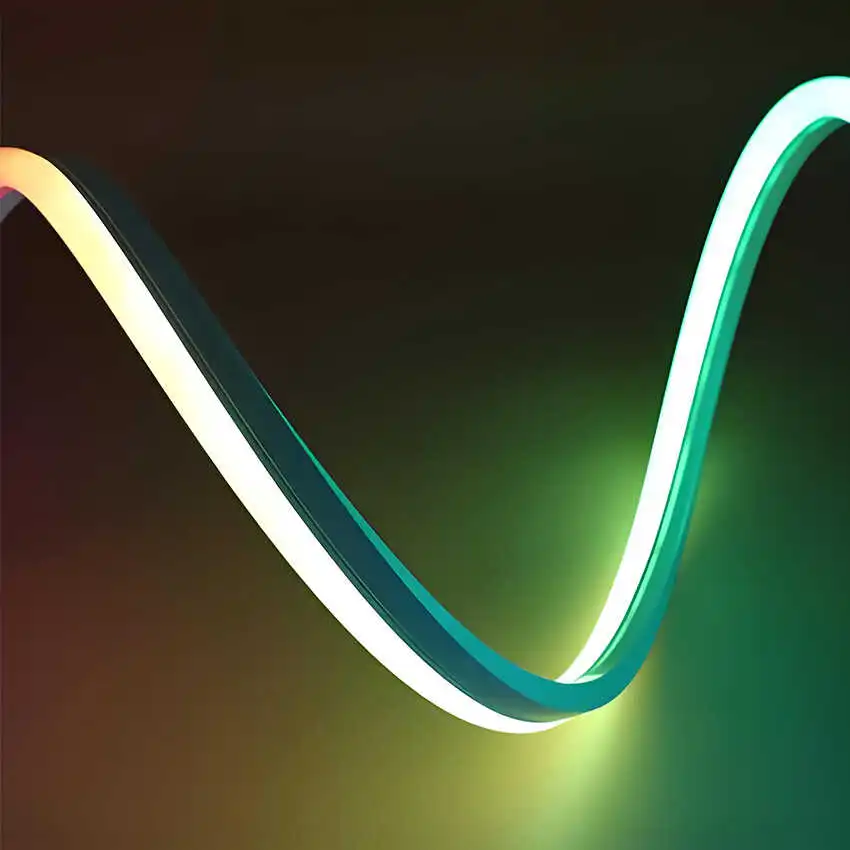
A continuous light line across two planes
A cove can curve around a column and then rise toward the ceiling. NPHIS 24V 3D bend LED neon flex follows both turns while keeping the lit face oriented toward the viewer. Choose the square profile that fits the channel and the tightest curve on your drawing.
- Top and side bending in the same run
- 10 × 10, 12 × 12 and 16 × 16 mm co-extruded silicone profiles
- CRI ≥90 white light at 9.6 W/m
YEARS EXPERIENCE
0
+
GLOBAL CLIENTS
400
+
HOUR LIFESPAN
0
K
COUNTRIES SERVED
40
+
PRODUCT BASICS
What is 3D bend LED neon flex?
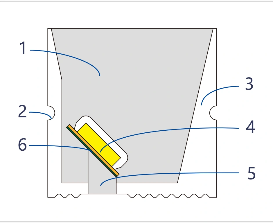
A 3D bend silicone neon flex is a flexible linear light that can curve both toward the back of the emitting face and sideways along the mounting surface. The silicone diffuser forms a continuous line of light. Plan each turn with the emitting face pointing where the light is needed.
➊. marks the emitting face
➋. the clip groove
➌. the light-blocking side. Inside the profile
➍. LED light strip positioned at a 45-degree angle
➎. the cut-mark window
➏. the reinforcement strip.
Keep the profile free of twist. Rotating one end to aim the light can strain the circuit board even when the curve looks gentle.
PROJECT PLANNING
Where a 3D bend solves a layout problem
Ceiling cove to wall return
Mark where the curve changes plane. A top-bending run can follow an arch, but a second turn across the wall calls for side bending as well.
The tightest part of the outline
Dimension the smallest curve on the drawing and mark whether it is a radius or diameter. This lets us check the bend before the channel is fabricated.
A channel already cut to size
Send the inside width and depth of the recess. Leave room at each end for the cap and cable exit, then test a sample in the actual profile before the full run.
TECHNICAL DATA
Compare 1010, 1212 and 1616 profiles
Not sure whether your curved drawing requires top-bend, side-bend, or dual-plane 3D bending? Read our engineering guide on how to specify 3D bend neon flex for architectural lighting before ordering a sample.
| Specification | 1010-3D | 1212-3D | 1616-3D |
|---|---|---|---|
| Profile size | 10 × 10 mm | 12 × 12 mm | 16 × 16 mm |
| Input / rated power | 24 V DC / 9.6 W/m | 24 V DC / 9.6 W/m | 24 V DC / 9.6 W/m |
| Luminous flux | 360–500 lm/m | 380–520 lm/m | 320–490 lm/m |
| Luminous efficacy | 37–50 lm/W | 38–52 lm/W | 32–49 lm/W |
| White CCT options | 3000 K ±150 K, 4000 K ±200 K, 6000 K ±300 K | 3000 K ±150 K, 4000 K ±200 K, 6000 K ±300 K | 3000 K ±150 K, 4000 K ±200 K, 6000 K ±300 K |
| CRI (Ra) | ≥90 | ≥90 | ≥90 |
| LED package / density | SMD 2835 / 168 LEDs/m | SMD 2835 / ≥120 LEDs/m | SMD 2835 / ≥120 LEDs/m |
| PCB width / weight of neon flex | 5 mm / 114 g/m | 5 mm / 195 g/m | 8 mm / 305 g/m |
| Cut interval | 35 mm. At the PCB marks | 50mm. At the PCB marks. Confirm pitch for the order. | 50mm. At the PCB marks. Confirm pitch for the order. |
| Beam angle | See photometric plot in PDF | 120° | 120° |
| Color consistency, bare strip | Unspecified | SDCM <3 | SDCM <3 |
| Operating temperature | −40 to 120 °C | −40 to 120 °C | −40 to 120 °C |
| Ingress protection | Wrap-around end caps IP65/IP66. Trimless end caps IP66/IP67. | IP67 | IP67 |
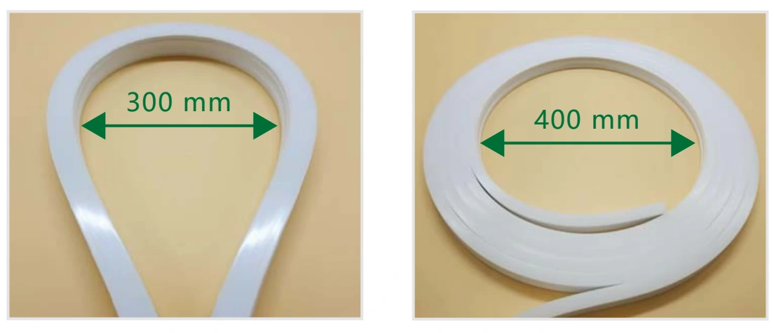
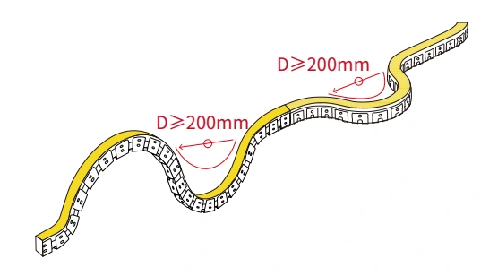
| Minimum bend diameter in the illustrated installation | ≥200 mm in the bendable channel shown | 300 mm bending back away from the emitting face | 320 mm bending back away from the emitting face |
| Minimum coiling diameter, 5 m reel | Unspecified | 400 mm, cut window inward | 430 mm, cut window inward |
Bend dimensions are diameters. For outdoor work, identify the end-cap style, cable entry and field cuts when requesting the assembled configuration.
PROFILE SELECTION
Top bend, side bend or 3D bend?
Trace the light line with the emitting face marked. A single-plane profile is a practical choice when every turn stays in its bending plane. Use the 3D profile when the route changes planes and the light must follow it.
| Selection point | Top bend | Side bend | 3D bend |
|---|---|---|---|
| Bend direction | Up or down relative to the emitting face | Left or right relative to the emitting face | Top and side bends along one run |
| Typical route | An arch in a single vertical plane | A flat logo or curved perimeter on a wall | A ceiling wave that turns onto a wall or around a column |
| What to check | Orient the face before setting the arch diameter. | Keep the full outline in the supported plane. | Mark each change of plane and the smallest diameter. Keep the profile free of twist. |
| When it makes sense | The entire route follows a top bend. | All turns can follow a side bend. | Both bend directions are needed and the chosen model fits the tightest curve. |
For a single-plane route, browse the NPHIS silicone LED neon flex range for other profile options.
STRUCTURE & INSTALLATION
Mounting and bending 3D LED neon flex
1. Select the mounting hardware
Use clips for local support, a straight aluminum channel for a straight run, or a bendable channel for a shaped recess. Match mounting channels for 3D neon flex to the selected size. Fix the hardware with screws, then press the profile into place with the emitting face oriented as drawn.

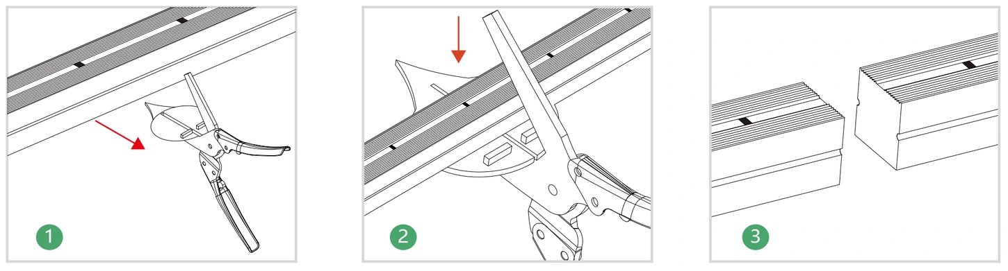
2. Cut at the PCB mark
Disconnect power. The 1010 has a 35 mm cut interval. On 1212 and 1616, locate the PCB mark through the window before cutting. Order lengths to suit those marks so the final segment lands where the drawing requires.
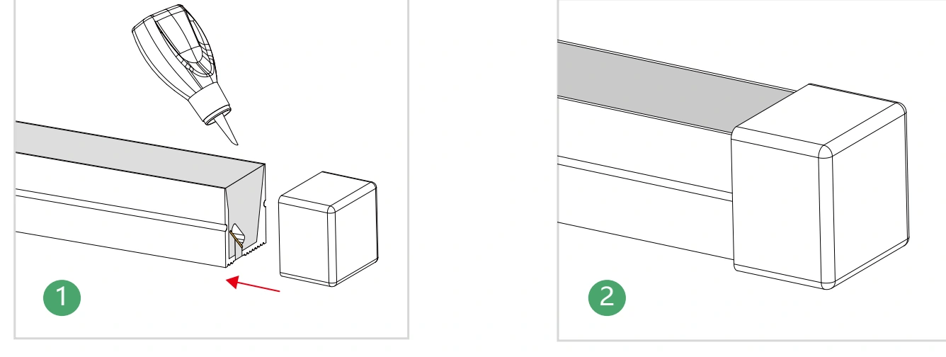
3. Fit the end cap and cable
Choose the cable exit before fixing the last section. Verify polarity, insulate the connection and use the cap and adhesive specified for that profile. The 1212 and 1616 instructions call for 2–3 hours undisturbed before handling a glued cap.
4. Check the bend and power feed
Dry-fit the tightest curve with the channel and end caps in place. Follow the orientation in the model drawing and keep tension off the cable. Use a 24 V DC supply. The 1010 wiring example shows a center feed with 5 m on each side. For another feed layout or model, send the individual run lengths for review.

PRODUCTION & DOCUMENTATION
Equipment and compliance documents
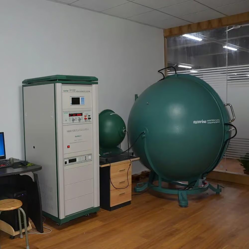
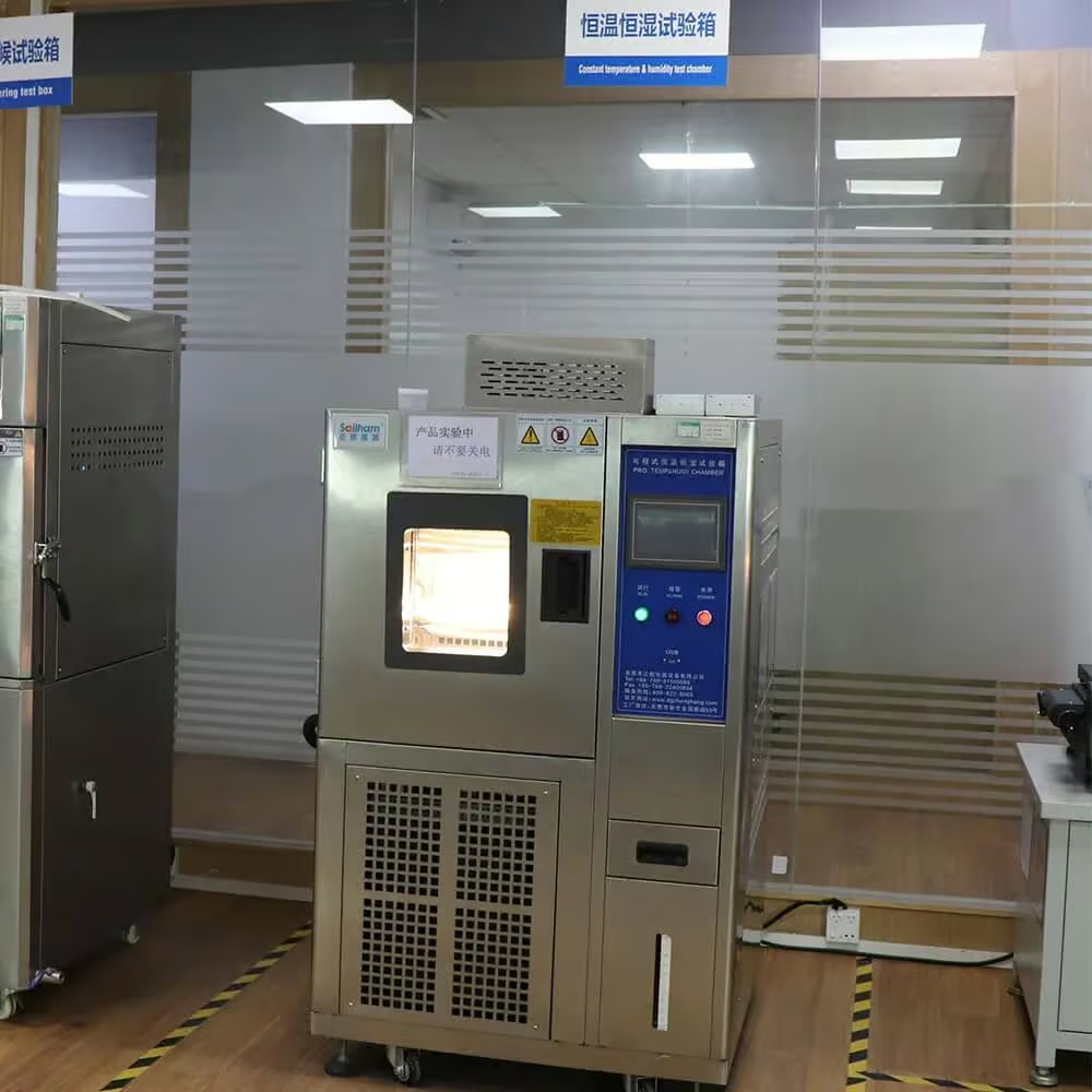
An integrating sphere measures light output and color. The SMT line places LEDs on the circuit board, and the temperature and humidity chamber supports environmental testing. When requesting test data, specify the profile, CCT and operating conditions you want evaluated.
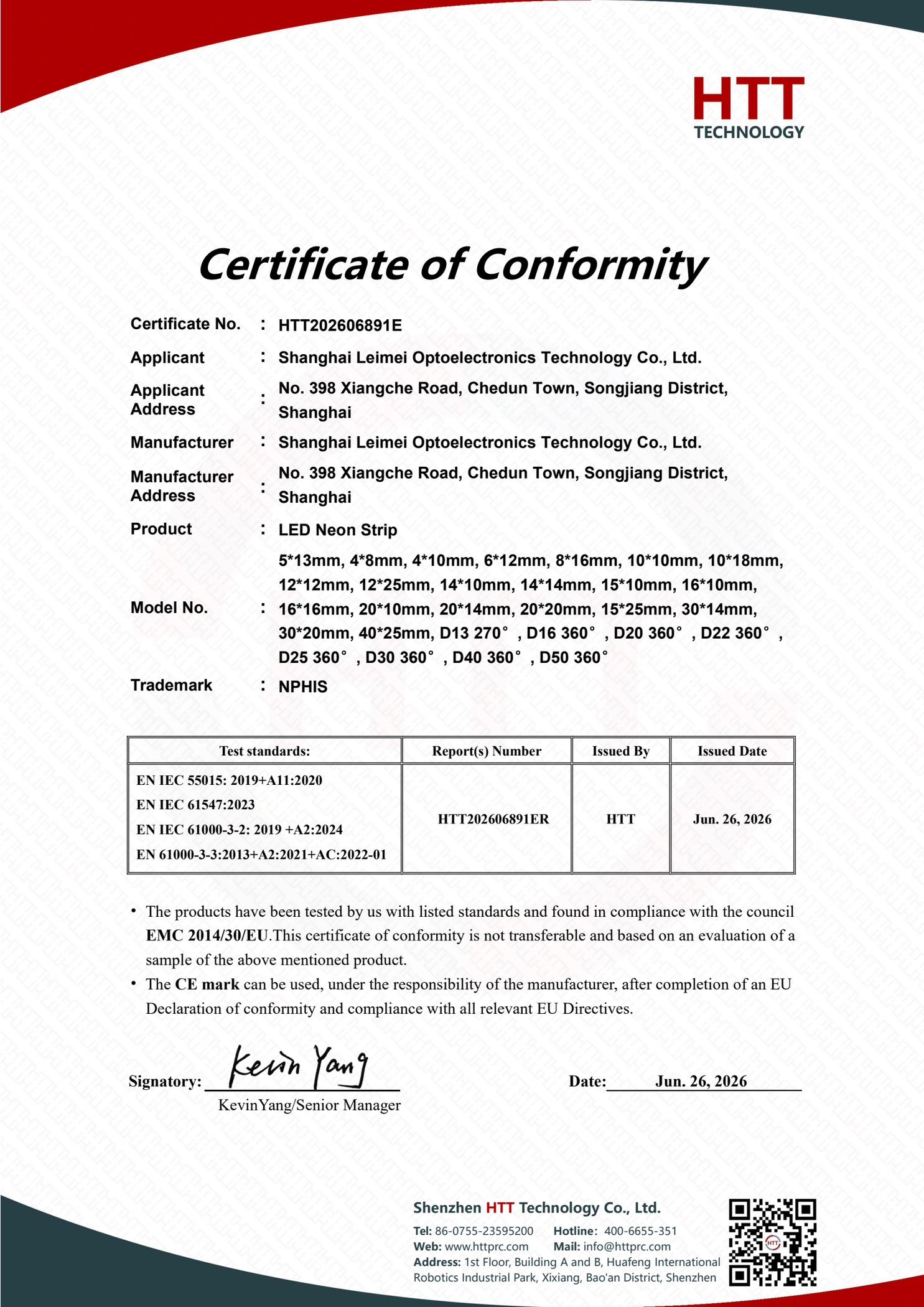
EMC and RoHS documents for NPHIS LED Neon Strip
The documents name Shanghai Leimei Optoelectronics Technology Co., Ltd. as applicant and manufacturer and identify NPHIS as the trademark. Their model lists include 10 × 10, 12 × 12 and 16 × 16 mm. Send the ordered configuration and destination market so we can match the documentation to your purchase.

FAQs: Bespoke Neon Flex Strip Light
3D LED Neon Strip: Expert QA
Find reliable technical answers for 3D LED neon flex and silicone LED neon flex, including DMX512 controller selection, RGBW addressable pixel effects, IP68 waterproof outdoor wiring, DC24V DC48V power supply design, signal transmission solutions, custom cutting options and building facade lighting installation tips. This FAQ is built for lighting contractors, facade lighting designers, signage manufacturers and commercial installers sourcing premium addressable 3D LED neon flex for architectural lighting, retail displays, entertainment lighting and outdoor advertising sign projects.
01. What is 3D bend LED neon flex, and when should I use it?
3D bend LED neon flex combines top and side bending in one continuous light run. It is useful when a lighting route changes planes, such as a ceiling cove that turns onto a wall or curves around a column. NPHIS offers 24 V DC silicone profiles in 10 × 10, 12 × 12 and 16 × 16 mm sizes. Choose the profile around the emitting-face direction and the tightest curve on your drawing. The flex must remain free of twist.
02. How do I choose between 1010, 1212 and 1616 profiles?
Start with the available channel space, desired line width and minimum bend. Our published light-output ranges are 360–500 lm/m for 1010, 380–520 lm/m for 1212 and 320–490 lm/m for 1616, with CRI Ra ≥90. A wider profile therefore does not automatically provide more light. White options include 3000 K, 4000 K and cool white in the 6000–6500 K range. Confirm the ordered nominal CCT and compare samples before combining different sizes in one visible installation.
03. What is the minimum bending radius of NPHIS 3D neon flex?
The installation drawings specify minimum bending diameters: 200 mm for 1010 in the illustrated bendable channel, 300 mm for the illustrated 1212 back bend, and 320 mm for the illustrated 1616 back bend. These correspond to radii of 100, 150 and 160 mm in those configurations. They are not universal limits for every bending direction. The separate 5 m coiling diameters are 400 mm for 1212 and 430 mm for 1616, with the cut-mark window facing inward. Follow the model drawing and avoid twisting or sharp folds.
04. Can I cut the neon flex to fit my project?
Yes. The 1010 profile has a 35 mm cut interval. The current 24 V, 120 LEDs/m versions of 1212 and 1616 have a 50 mm cut interval. Disconnect power and cut only at the marked PCB cutting line, visible through the cut-mark window. Include the end caps and cable exits when specifying the finished installation length. Each cut end needs the correct termination and sealing procedure; cutting and adding a cap alone does not establish an IP rating.
05. Is NPHIS 3D LED neon flex waterproof and suitable for outdoor use?
Outdoor suitability depends on the complete assembled configuration. The 1212 and 1616 datasheets list IP67. For 1010, the listed ratings vary by end-cap design: IP65/IP66 for wrap-around caps and IP66/IP67 for trimless caps. Confirm the cap, cable entry, connectors and any field cuts for your order. IP67 addresses temporary immersion, so it should not be treated as approval for permanent underwater or swimming-pool use. The power supply and controller need their own suitable protection; the neon flex rating does not cover them.
06. What power supply does this 24 V neon flex need?
Use a matching 24 V DC constant-voltage power supply. At the published rating of 9.6 W/m, a nominal 5 m length has a calculated load of 48 W, or 2 A at 24 V. These are load calculations, not a complete driver selection. Allow for cable losses, control equipment and the driver’s temperature-dependent output rating. NPHIS can supply compatible Mean Well LED power supplies matched to the project load, installation environment and dimming method. Never connect the neon flex directly to mains AC.
07. Can I connect several lengths for a 10 m or 20 m installation?
Plan the feed arrangement before joining the lengths. The 1010 wiring drawing shows a center feed with 5 m on each side, totaling 10 m; it does not establish a 10 m single-end feed. A nominal 20 m project at 9.6 W/m has a calculated total load of 192 W, or 8 A at 24 V, but sufficient power-supply capacity alone does not establish an acceptable run length. Send the profile, individual section lengths and cable distances so the feed points and voltage drop can be reviewed for that layout.
08. Should I use adhesive, clips or a channel to mount 3D neon flex?
Use mounting hardware matched to the selected profile: clips for local support, straight aluminum channels for straight runs, or bendable channels for shaped routes. The NPHIS installation instructions show the hardware secured with screws before the flex is pressed into place. End-cap adhesive serves a sealing function and should not be assumed to replace mechanical support. Allow space for caps and cable exits, support the flex without pulling on its leads, and trial-fit the tightest curve before completing the installation.
09. Can NPHIS 3D neon flex be dimmed with PWM, DALI or 0–10V controls?
Yes. These 24 V white-light models can be configured for PWM, DALI or 0–10V dimming with a compatible external driver or controller. The control interface belongs to the selected driver/controller; it is not a signal input on the neon flex itself. Specify your control system, total load and required dimming behavior when ordering. If the installation will be filmed, evaluate the complete setup at the intended dimming levels and camera settings. RGB color chasing and individually addressable effects require a separately specified product and control system.
10. What warranty does NPHIS provide, and how is it different from LED lifespan?
NPHIS 3D LED neon flex carries a standard 3-year warranty. Eligible custom orders can be supplied with an extended warranty of up to 5 years, subject to the configuration and terms confirmed in the quotation. Warranty coverage is a commercial commitment; operating life also depends on temperature, driver performance, installation and environmental exposure. Any project-specific lifetime requirement should be assessed separately using the relevant model and test conditions. Confirm the coverage of any bundled power supply and controller in the same quotation.
PROJECT INQUIRY
Request a quote for your 3D neon flex run
In the subject, include the profile size or project name. In the message, specify the tightest bend and whether you measured radius or diameter, the length of each section, your preferred white CCT, the installation environment and the total quantity. Paste a drawing link if available, or send the drawing when our team replies.
BUYER & INSTALLER GUIDES