
ในการตรวจสอบโครงการออกแบบภายนอกอาคารเมื่อเร็วๆ นี้ คำถามหลักไม่ใช่ว่าซิลิโคนนีออนเฟล็กซ์จะสามารถโค้งงอตามรูปทรงได้หรือไม่ แต่เป็นว่า... เปรียบเทียบระหว่างไฟนีออน LED 12V กับ 24V จะทำให้ส่วนสุดท้ายมีความสว่างเท่ากับส่วนแรก ในขณะเดียวกันก็คำนึงถึงตำแหน่งของแหล่งจ่ายไฟและเส้นทางของสายเคเบิลให้ใช้งานได้จริง จากมุมมองของโรงงานของเรา การตัดสินใจนี้ขึ้นอยู่กับประเด็นทางวิศวกรรมสี่ประการ ได้แก่ ความแม่นยำในการตัด กระแสไฟฟ้าที่ใช้งาน แรงดันตก และการวางแผนโซนพลังงาน.
แรงดันไฟฟ้าที่ระบุในใบเสนอราคาเป็นเพียงจุดเริ่มต้นเท่านั้น เรายังต้องการข้อมูลรายละเอียดเพิ่มเติม เช่น รูปทรง กำลังไฟฟ้าต่อเมตร การจัดเรียงสี ทิศทางการป้อนสายไฟ ความยาวสายไฟ และอุณหภูมิในการติดตั้ง ก่อนที่จะยืนยันระยะการใช้งานสูงสุดที่เหมาะสมได้.
| เงื่อนไขโครงการ | ตัวเลือกเริ่มต้น | ต้องตรวจสอบก่อนสั่งซื้อ |
|---|---|---|
| ตัวอักษรสั้น เส้นโค้งกระชับ | 12V อาจจะพอดี | หน่วยตัด, ทิศทางการดัด, กำลังไฟฟ้าจริง (W/m) |
| การวิ่งเชิงเส้นแบบคงที่ที่ยาวขึ้น | โดยทั่วไปแล้ว 24 โวลต์จะเป็นจุดเริ่มต้น | ข้อจำกัดการป้อนแบบปลายเดียว/สองปลายสำหรับรุ่นที่ระบุ |
| ด้านหน้าอาคาร สะพาน RGBW โหลดสูง | ระบบ 24V พร้อมแผนผังโซนพลังงาน | การคำนวณแรงดันตก การหาจุดจ่ายไฟ และการเข้าถึงบริการ |
สารบัญ
สายไฟนีออน LED 12V เทียบกับ 24V: ตัดสินใจได้ในตารางเดียว
| ปัจจัยการคัดเลือก | 12 โวลต์ | 24 โวลต์ | นัยทางวิศวกรรม |
|---|---|---|---|
| กระแสโหลดเดียวกัน | สูงกว่า | ประมาณครึ่งหนึ่งของกระแสไฟ 12V | โดยปกติแล้ว แรงดัน 24V จะลดกระแสไฟป้อนเข้าสำหรับกำลังวัตต์เท่าเดิม. |
| ความไวต่อแรงดันตก | เปอร์เซ็นต์การลดลงที่สูงกว่าสำหรับแรงดันไฟฟ้าที่หายไปเท่ากัน | อัตราการลดลงของแรงดันไฟฟ้าที่ต่ำกว่าสำหรับแรงดันไฟฟ้าที่ลดลงเท่าเดิม | แรงดันไฟฟ้า 24V โดยทั่วไปจะรักษาความสว่างและความสม่ำเสมอของสีได้ดีในวงจรที่ยาวกว่า. |
| ตัดตามความยาว | โดยทั่วไปจะสั้นกว่าและแม่นยำกว่า | โดยทั่วไปจะใช้เวลานานกว่านั้น ขึ้นอยู่กับการออกแบบวงจร | ตรวจสอบขนาดการตัดจริงเป็นมิลลิเมตร ไม่ใช่แค่แรงดันไฟฟ้าอย่างเดียว. |
| จำนวนโซนพลังงาน | อาจจำเป็นต้องกำหนดโซนเพิ่มเติมสำหรับการวิ่งระยะยาว | อาจมีจำนวนโซนน้อยลงได้ | จำนวนวัตต์สุดท้ายขึ้นอยู่กับกำลังวัตต์ต่อเมตร ความต้านทานของสายเคเบิล วิธีการป้อนไฟ และระดับการหรี่ไฟที่อนุญาต. |
| เหมาะสมที่สุด | ตัวอักษร โลโก้ รูปทรงขนาดเล็ก เครื่องหมายเน้นเสียงขนาดกะทัดรัด | ด้านหน้าอาคาร พื้นที่ค้าปลีก ซุ้มร้านอาหารและโรงแรม และองค์ประกอบเชิงเส้นยาวๆ | เลือกใช้ระบบไฟฟ้าโดยรวมทั้งหมด แทนที่จะเลือกเฉพาะแรงดันไฟฟ้าเพียงอย่างเดียว. |
สำหรับโหลดไฟฟ้าที่เท่ากัน การเพิ่มแรงดันไฟฟ้าขณะใช้งานจะทำให้กระแสไฟฟ้าลดลง:
ตัวอย่างเช่น โหลด 120 วัตต์ จะใช้กระแส 10 แอมป์ ที่แรงดัน 12 โวลต์ แต่จะใช้กระแสเพียง 5 แอมป์ ที่แรงดัน 24 โวลต์ ความแตกต่างนี้ส่งผลต่อขนาดสายไฟ การรับโหลดของขั้วต่อ ความจุของตัวควบคุม การเลือกฟิวส์ และจำนวนจุดจ่ายไฟ.
การสูญเสียพลังงานในสายเคเบิลจะเพิ่มขึ้นตาม:
ดังนั้น การลดกระแสไฟฟ้าลงครึ่งหนึ่งสามารถลดการสูญเสียเนื่องจากความต้านทานของสายเคเบิลได้อย่างมาก เมื่อความต้านทานของตัวนำยังคงไม่เปลี่ยนแปลง อย่างไรก็ตาม นี่ไม่ได้หมายความว่าหลอดไฟนีออน 24V ทุกหลอดจะใช้งานได้นานขึ้นเป็นสองเท่า ความต้านทานภายในของแผงวงจรพิมพ์ (PCB) การจัดกลุ่ม LED กำลังวัตต์ สี และสภาวะความร้อนนั้นขึ้นอยู่กับผลิตภัณฑ์แต่ละชนิด.
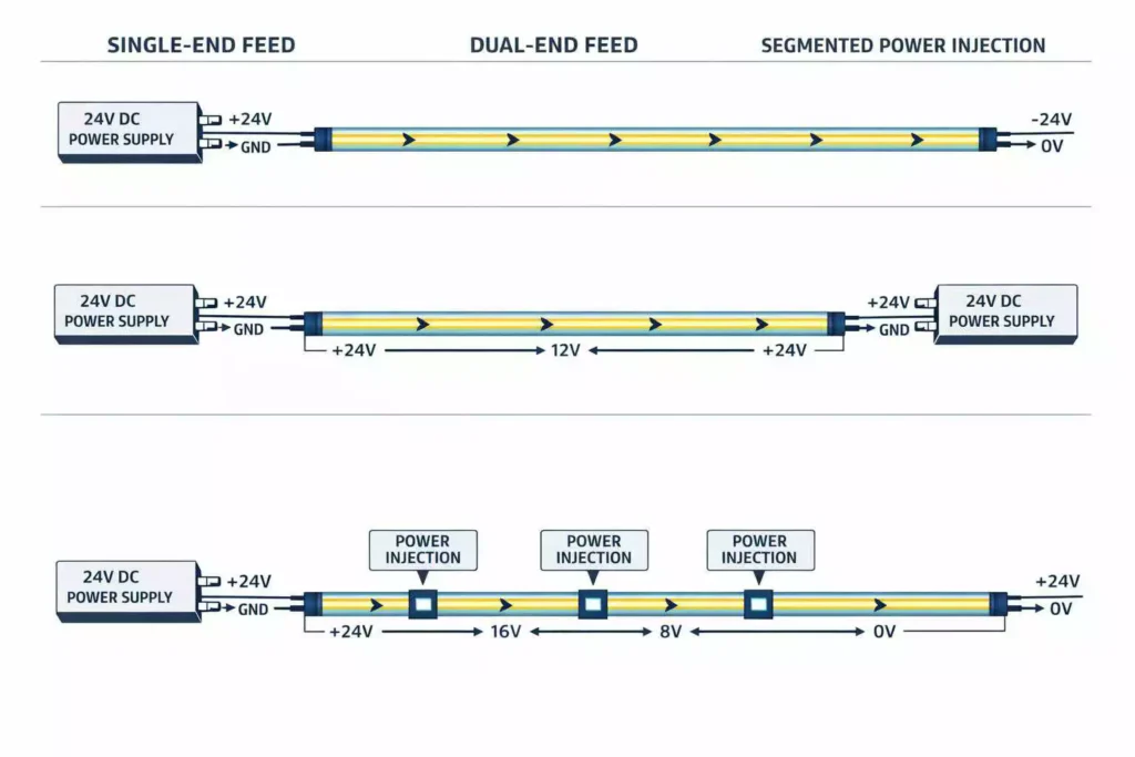
แรงดันไฟฟ้าตกเป็นปัญหาของระบบ ไม่ใช่ปัญหาที่เกิดจากความยาวของม้วนเทป
แรงดันตกเกิดขึ้นตลอดทั้งวงจร สามารถเกิดขึ้นได้ในแผงวงจรพิมพ์แบบยืดหยุ่น (Flex PCB), สายต่อพ่วง, ขั้วต่อ, จุดบัดกรี, ขั้วต่อของตัวควบคุม และอุปกรณ์กระจายไฟ.
ด้วยเหตุนี้ ข้อความต่างๆ เช่น “สูงสุด 5 เมตร” หรือ “สูงสุด 10 เมตร” จึงเป็นเพียงแนวทางการคัดเลือกเบื้องต้นเท่านั้น ไม่ใช่การรับประกันการติดตั้งในทุกกรณี.
ระยะเวลาการใช้งานจะเปลี่ยนแปลงไปตาม:
- กำลังไฟจริงของผลิตภัณฑ์ต่อเมตร
- น้ำหนักทองแดงและความกว้างของตัวนำในแผ่น PCB
- การกำหนดค่าแบบขาวดำ, RGB, RGBW หรือพิกเซล
- กระแสไฟฟ้าใช้งานช่องสีขาว
- การจ่ายไฟแบบปลายเดียวหรือสองปลาย
- ขนาดสายเคเบิลและความยาวสายป้อน
- ความต้านทานของตัวเชื่อมต่อและข้อต่อ
- อุณหภูมิแวดล้อมและอุณหภูมิภายในพื้นที่ปิด
- ความแตกต่างของความสว่างที่ยอมรับได้เมื่อสิ้นสุดการทำงาน
ม้วนสายไฟยาว 10 เมตร ไม่ได้หมายความว่าสายไฟทั้ง 10 เมตรจะต้องจ่ายไฟจากปลายด้านเดียวเสมอไป ความยาวของม้วนสายไฟมักเป็นข้อกำหนดด้านบรรจุภัณฑ์ ในขณะที่ความยาวของสายที่จ่ายออกมาเป็นข้อกำหนดด้านไฟฟ้า.
ควรวัดแรงดันไฟฟ้าที่ส่งไปยังสายไฟนีออนขณะใช้งานเต็มกำลังด้วย การวัดค่า 24V ที่แหล่งจ่ายไฟขณะไม่มีโหลดนั้น ไม่ได้แสดงถึงแรงดันไฟฟ้าที่ส่งไปยังส่วนสุดท้ายของหลอดไฟหลังจากหักลบการสูญเสียในสายเคเบิลและตัวผลิตภัณฑ์แล้ว.
สำหรับระบบจ่ายไฟแบบสองทางและโซนจ่ายไฟแบบฉีดเข้าขั้ว ขั้วไฟฟ้าต้องคงที่เสมอ วงจรต้องมีการติดตั้งฟิวส์และกระจายตามแบบที่ได้รับการอนุมัติ ไม่ควรต่อแหล่งจ่ายไฟแยกต่างหากขนานกันบนตัวนำต่อเนื่องเดียวกัน เว้นแต่สถาปัตยกรรมพลังงานได้รับการออกแบบมาโดยเฉพาะสำหรับการจัดเรียงแบบนั้น.
เลือกใช้ 12V เมื่อความแม่นยำในการตัดมีความสำคัญมากกว่าความยาวในการตัด
สายไฟนีออน 2V ไม่ใช่สินค้าคุณภาพต่ำ มักถูกเลือกใช้เพราะโครงสร้างวงจรสามารถรองรับชิ้นส่วนที่ตัดสั้นกว่าได้.
อย่างไรก็ตาม แรงดันไฟฟ้าเพียงอย่างเดียวไม่ได้รับประกันความยาวในการตัดที่แน่นอน จำนวน LED การจัดกลุ่มแบบอนุกรม การจัดวางตัวต้านทาน การออกแบบ PCB และระยะห่างระหว่าง LED เป็นตัวกำหนดช่วงความยาวในการตัดที่แท้จริง.
ตัวอักษรและโลโก้แบบย่อ
ตัวอักษรขนาดเล็กและโลโก้ที่มีรายละเอียดมาก อาจมีส่วนตรงสั้นๆ จำนวนมาก ชิ้นส่วนที่ตัดยาวเกินไปอาจทำให้เกิดช่องว่างสีดำที่มุม หรือบังคับให้ผู้ติดตั้งต้องแก้ไขงานศิลปะดั้งเดิม.
สำหรับใบสมัครเหล่านี้ เราจะตรวจสอบ:
- เส้นที่สั้นที่สุดในภาพวาด
- ตำแหน่งจุดตัดรอบตัวอักษรแต่ละตัว
- ทางออกสายเคเบิลระหว่างส่วนต่างๆ
- ความเสี่ยงจากจุดมืดบริเวณฝาปิดปลายและจุดเชื่อมต่อ
- รัศมีโค้งขั้นต่ำที่อนุญาต
ผู้ซื้อควรจัดเตรียมไฟล์ภาพเวกเตอร์หรือแบบร่างที่มีขนาดกำกับ ภาพถ่ายที่ไม่มีมาตราส่วนไม่เพียงพอสำหรับการวางแผนการตัด.
ของตกแต่งภายในขนาดกะทัดรัด
ระบบไฟ 12V เหมาะสำหรับงานตกแต่งจอแสดงผล เคาน์เตอร์ขนาดเล็ก รูปทรงตกแต่งผนัง และชิ้นส่วนตกแต่งตู้ขนาดสั้น โครงการเหล่านี้มักมีความยาวแต่ละชิ้นจำกัด และสายไฟหลักค่อนข้างสั้น.
แหล่งจ่ายไฟจะต้องยังคงเข้าถึงได้และมีขนาดที่เหมาะสม การวางไดรเวอร์ที่มีขนาดใหญ่เกินไปไว้ในช่องปิดสนิทที่ไม่มีการระบายอากาศอาจก่อให้เกิดปัญหาด้านความน่าเชื่อถือทางความร้อนอีกประการหนึ่งได้.
ลดปริมาณเศษวัสดุเหลือทิ้ง
ความยาวของหน่วยตัดมีผลต่อปริมาณวัสดุที่ได้ หากรูปทรงหนึ่งต้องการความยาว 230 มม. แต่ผลิตภัณฑ์สามารถตัดได้ทุกๆ 100 มม. เท่านั้น ความยาวส่วนที่ใช้งานได้จริงอาจต้องเป็น 200 มม. หรือ 300 มม. เมื่อตัดเป็นตัวอักษรหลายร้อยตัว อาจทำให้เกิดของเสียจำนวนมากหรือการเปลี่ยนแปลงการออกแบบที่เห็นได้ชัด.
ก่อนอนุมัติรุ่น 12V โปรดตรวจสอบสิ่งต่อไปนี้:
- รอยตัด: ขอทราบช่วงระยะการตัดในหน่วยมิลลิเมตร และแบบร่าง PCB ที่มีการทำเครื่องหมายไว้แล้ว.
- รัศมีโค้งขั้นต่ำ: ตรวจสอบทั้งรัศมีที่ระบุและทิศทางการดัดให้ถูกต้อง.
- ทิศทางการออกจากตัวเชื่อมต่อ: ตรวจสอบให้แน่ใจว่าสายเคเบิลออกมาจากด้านหน้า ด้านข้าง หรือด้านล่าง เทียบกับช่องยึดและจุดเข้าถึงพื้นที่ติดตั้ง.
- สิ้นสุดการรักษา: ระบุความยาวของฝาปิดปลายและระยะเผื่อบริเวณสีเข้มในแบบร่างด้วย.
- ค่าความคลาดเคลื่อนของกำลังวัตต์: ใช้ค่าการผลิตที่ได้รับการยืนยันแล้วสำหรับการคำนวณแหล่งจ่ายไฟและสายเคเบิล.
เลือกใช้ 24V สำหรับการใช้งานเชิงเส้นเชิงพาณิชย์ระยะยาว
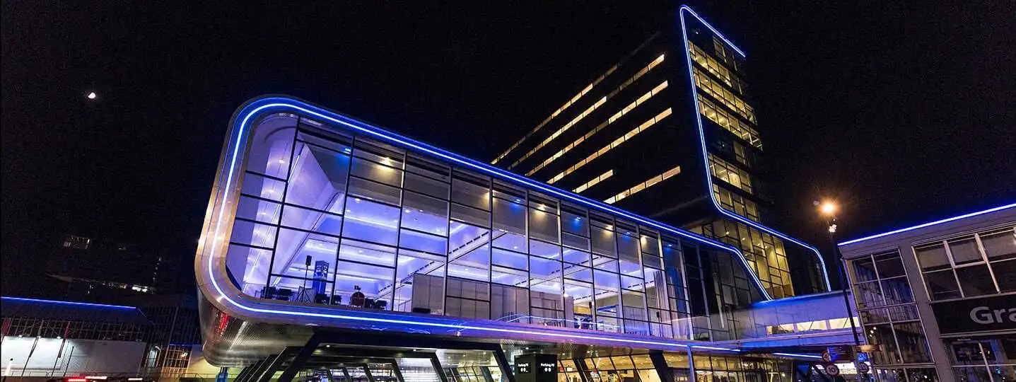
โดยปกติเราจะเริ่มต้นด้วยแรงดัน 24V สำหรับงานตกแต่งภายนอกอาคาร พื้นที่ค้าปลีก บริเวณทางเข้าออกโรงแรม ทางเดิน และงานติดตั้งไฟเชิงเส้นอื่นๆ ในเชิงพาณิชย์ เนื่องจากกระแสไฟที่ต่ำกว่าจะช่วยให้การวางแผนระบบจ่ายไฟง่ายขึ้น และลดภาระให้กับสายเคเบิล ตัวเชื่อมต่อ และเอาต์พุตของตัวควบคุม สำหรับโหลดที่เท่ากัน.
วิธีนี้มีประโยชน์อย่างยิ่งในกรณีที่ไม่สามารถติดตั้งแหล่งจ่ายไฟไว้ข้างๆ ส่วนแรกได้ทันที ถึงแม้จะต้องคำนวณสายป้อนแรงดันต่ำที่ยาวอยู่ แต่โดยทั่วไปแล้วแรงดัน 24V จะให้ทางเลือกที่ใช้งานได้จริงมากกว่าสำหรับวิศวกร.
การใช้งานทั่วไปในระบบ 24V ได้แก่:
- โครงร่างสถาปัตยกรรมสีขาวนิ่งยาว
- ขอบเพดานและผนังของร้านค้าปลีก
- โถงทางเข้าและทางเดินของโรงแรม
- ลักษณะภูมิทัศน์ภายนอก
- โครงร่างสะพานและพื้นที่สาธารณะ
- อุปกรณ์ RGBW หรืออุปกรณ์เปลี่ยนสีแบบกำหนดแอดเดรสได้
สำหรับการติดตั้งแบบควบคุม ผู้ซื้อสามารถตรวจสอบข้อมูลของเราได้ นีออนเฟล็กซ์ DMX512 RGBW 24V สำหรับโครงการเชิงพาณิชย์แบบไดนามิก. ระยะห่างระหว่างพิกเซล, การกำหนดแอดเดรส DMX, ความจุของตัวถอดรหัส, โครงสร้างข้อมูล และการจ่ายพลังงาน ต้องได้รับการประสานงานกันทั้งหมดก่อนเริ่มการผลิต.
ผลิตภัณฑ์ 24V นั้น ไม่ กำจัดปัญหาการจ่ายไฟเกิน การใช้งานต่อเนื่องเป็นเวลานานยังคงอาจทำให้เกิดปัญหาแสงหรี่ลง การเปลี่ยนแปลงจุดสีขาว หรือความไม่สม่ำเสมอของสีได้.
โหลด RGBW จำเป็นต้องได้รับการดูแลเป็นพิเศษ ฉากที่ใช้เพียงสีเดียวอาจผ่านการทดสอบในสถานที่ แต่การใช้ RGBW ที่มีเอาต์พุตเต็มประสิทธิภาพอาจเผยให้เห็นสายเคเบิลที่ไม่เหมาะสมหรือตัวควบคุมที่รับภาระเกินกำลัง ดังนั้นเราจึงคำนวณและทดสอบโดยใช้ฉากกรณีเลวร้ายที่สุดที่กำหนดไว้ ไม่ใช่เพียงแค่เอฟเฟกต์ที่ตั้งโปรแกรมไว้ตามปกติ.
โปรดดูบทความของเรา:DMX LED RGBW นีออนเฟล็กซ์ สำหรับไฟประดับอาคารและไฟส่องสว่างเพื่อความบันเทิง
เลือกขนาดแหล่งจ่ายไฟและวางแผนจุดจ่ายไฟ
สำหรับการกำหนดขนาด PSU เบื้องต้น เราใช้:
การหารด้วย 0.80 จะได้ค่า headroom ในการใช้งานประมาณ 20% ตัวอย่างเช่น สายไฟนีออนยาว 20 เมตร กำลังไฟ 10 วัตต์ต่อเมตร จะสร้างโหลดโดยประมาณ 200 วัตต์:
ระยะห่างดังกล่าวช่วยป้องกันการใช้งานอย่างต่อเนื่องที่พิกัดกำลังสูงสุดที่ระบุไว้บนแผ่นป้ายของตัวขับมอเตอร์ นอกจากนี้ยังช่วยเผื่อความคลาดเคลื่อนของผลิตภัณฑ์และสภาวะการใช้งานตามปกติอีกด้วย.
อย่างไรก็ตาม การมีกำลังสำรองไม่ได้หมายความว่าเราสามารถละเลยเรื่องการลดกำลังเนื่องจากความร้อนได้ กำลังขับของแหล่งจ่ายไฟอาจลดลงได้เนื่องจากอุณหภูมิแวดล้อมสูง การระบายอากาศไม่ดี การออกแบบตัวเครื่อง หรือเส้นโค้งการลดกำลังเฉพาะของผู้ผลิต.
ควรแบ่งแหล่งจ่ายไฟออกเป็นโซนที่สามารถบำรุงรักษาได้ แทนที่จะรวมไว้ในวงจรขนาดใหญ่เพียงวงจรเดียวโดยไม่มีการวางแผนการบำรุงรักษา แต่ละโซนควรอยู่ภายในขีดความสามารถของแหล่งจ่ายไฟ ตัวควบคุม ขั้วต่อ ฟิวส์ และสายไฟป้อนไฟ.
Before Issuing a PO, Confirm:
- Maximum single-end feed length for the exact model and colour
- Maximum dual-end feed length and approved wiring method
- Power-injection spacing
- Cable conductor size and total feeder length
- Connector and extension-cable current ratings
- Full-load scenarios, especially RGBW full output
- PSU load percentage and thermal derating
- Controller or decoder current per channel
- Fuse protection for each distribution branch
- Voltage available at the first and last powered sections
- Outdoor PSU location, drainage, ventilation, and maintenance access
- Access to connectors and injection points after installation
Factory Verification: What Should Be Tested Before Production?
We recommend approving test evidence for the exact ordered model. A report for another profile, wattage, PCB, or LED configuration may not represent the product being purchased.
| Buyer question | Evidence to request | Selection impact |
|---|---|---|
| Will the end dim? | Exact-model voltage-drop test | Determines feed length, dual-feed suitability, and injection spacing. |
| Is batch brightness consistent? | Integrating-sphere record | Confirms lumen output, power, CCT, CRI, and batch consistency. |
| Is it stable in outdoor heat/cold? | Temperature-cycle record | Supports profile, material, cable, and installation-temperature selection. |
| Does bulk match the sample? | Aging record and pre-shipment sample comparison | Helps verify production stability before packing and shipment. |
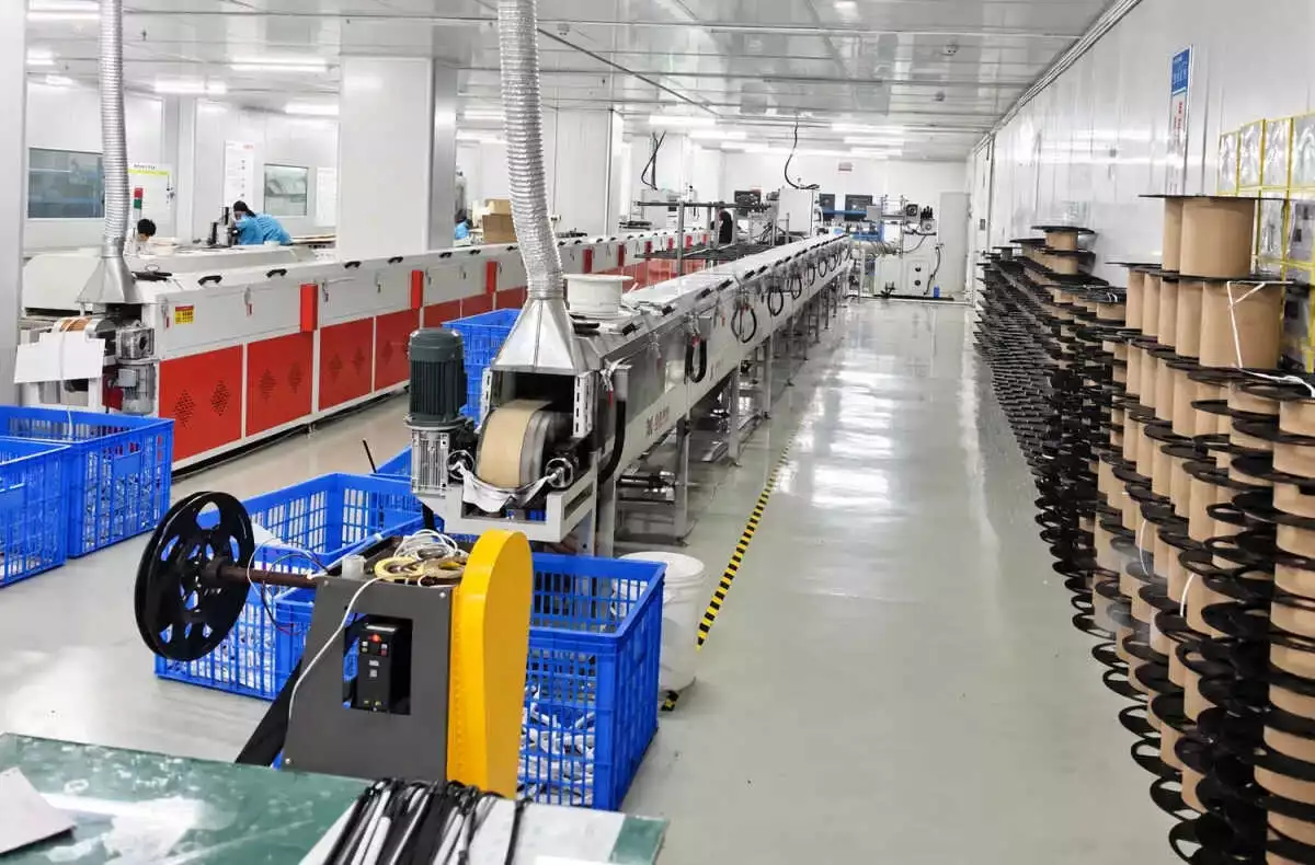
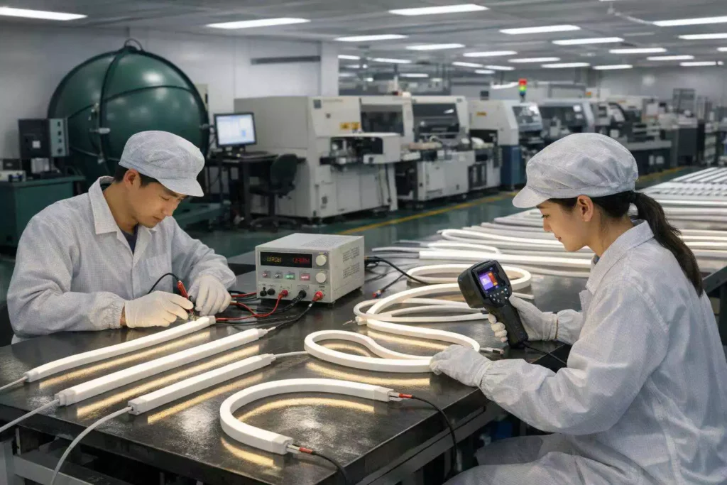
At our factory, the voltage-drop test should reproduce the intended configuration. This means using the correct length, input voltage, feed direction, and operating mode.
For a tunable or RGBW model, testing only a low-load colour is insufficient. We record input power and compare the beginning and end of the run under the agreed full-load condition.
Buyers can also ask for:
- Beginning-, middle-, and end-point voltage readings
- Illuminance or luminance comparison along the run
- Thermal images after stabilization
- CCT and colour-coordinate records
- Cable and connector temperature observations
- A production-sample aging report
- Photos showing the test length and feed method
EU Project Documentation Check — Do Not Treat Voltage as Compliance
Choosing 12V or 24V does not automatically make neon flex compliant for an EU project. Voltage is an electrical design parameter; compliance depends on the product configuration, intended use, supplied control gear, documentation, and the economic operator’s role.
EU Ecodesign requirements address energy-related performance and product information for in-scope light sources and separate control gears. The primary framework includes Commission Regulation (EU) 2019/2020. RoHS addresses restricted hazardous substances in electrical and electronic equipment; the European Commission’s RoHS guidance should be checked for current requirements and exemptions. These are different obligations, so a RoHS report does not prove Ecodesign conformity.
Before ordering, identify whether the neon flex is supplied as a light source, part of a containing product, or within a project-specific assembly. Confirm the applicable standards, test reports, labels, technical file, and Declaration of Conformity for the exact SKU. EU importers should also verify their own traceability, documentation-retention, labelling, and market-surveillance responsibilities. Project specifications may impose additional EMC, electrical-safety, IP, fire-performance, or building-code requirements.
Send Your Drawing for a Voltage and Power Plan
A useful RFQ needs more than total metres and a requested price. Send our engineering team the following details:
- Application type: facade, signage, cove, bridge, retail, or hospitality
- Dimensioned drawing, preferably PDF, DWG, DXF, or AI
- Individual section lengths rather than only total project length
- Required silicone profile and bending direction
- Light colour, CCT, RGB, RGBW, or addressable control requirement
- Target wattage per metre and required brightness
- Indoor or outdoor installation
- Ambient temperature and any enclosed mounting conditions
- Distance from the power room to each lighting zone
- Available cable routes and maintenance points
- Required connector exit direction
- Control protocol and planned controller
- Installation country and required compliance documents
- Sample approval and project delivery schedule
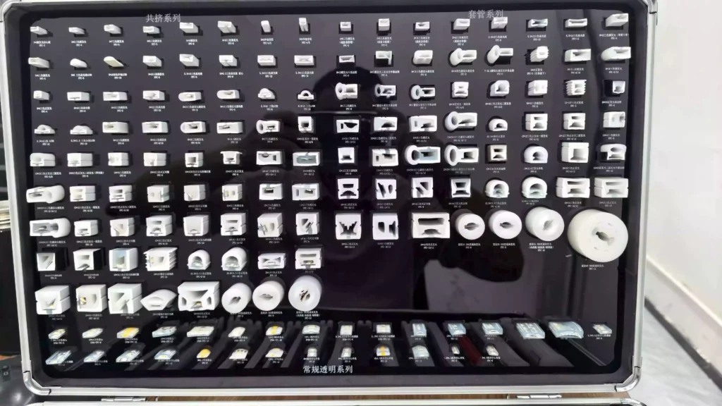
If the profile has not yet been finalized, buyers can compare silicone neon flex profiles and voltage options before requesting samples. For architectural planning considerations, our guide to silicone neon flex for architectural lighting also explains profile, bending, mounting, and specification factors.
Our project process is:
Drawing → Engineering Review → Sample → Power/Voltage-Drop Check → Bulk Production
During the engineering review, we divide the drawing into manufacturable sections. We then check cut points, bend direction, cable exits, feed distances, PSU capacity, controller loading, and service access. The resulting quotation can therefore identify the proposed voltage and power zones instead of leaving those decisions until installation.
โปรดดูบทความของเรา: Silicone Neon Flex for Architectural Lighting.
Conclusion — Choose the System, Not Just the Voltage
Choose 12V when short, precise cuts are more important than long feed lengths. Choose 24V as the starting point for commercial linear runs, but do not treat it as a substitute for cable calculations and power-injection planning. Always verify maximum lengths using test records for the exact neon flex model, wattage, colour, and feed configuration.
FAQs
❓️ Is 24V LED neon flex always brighter than 12V?
No. Voltage alone does not determine brightness. Brightness depends on LED efficiency, LED density, drive current, silicone optical transmission, profile size, and actual wattage per metre. A properly designed 12V model can be as bright as a 24V model. The main advantage of 24V is lower current for the same power, which usually makes voltage-drop and feeder-cable planning easier.
❓️ Can 24V LED neon flex run for 10 metres from one end?
It depends on the exact product. A 10-metre reel is not proof that the full reel can be powered from one end. We need to verify the profile, W/m, LED circuit, PCB resistance, colour, cable length, and permitted end-to-start brightness difference. Ask for an exact-model voltage-drop test before using a 10-metre single-end feed in a commercial project.
❓️ Does 12V LED neon flex have a shorter cutting length?
Often, but not always. The cutting interval is determined by the LED grouping and PCB circuit design. For letters and logos, request the cut unit in millimetres. We also recommend placing the cut points over the actual drawing before approving a sample.
❓️ How often should power be injected into LED neon flex?
There is no universal injection interval. Injection spacing depends on voltage, wattage per metre, product resistance, feeder cable, colour mode, and the acceptable voltage at the end of each zone. For RGBW or addressable products, the calculation should use the maximum intended load. A low-power animation does not represent the worst-case electrical condition.
❓️ Can we connect both ends of LED neon flex to one power supply?
A dual-end feed may be used when the exact product and wiring plan permit it. Both connections must have the correct polarity and adequate conductor size. The installation should follow the approved circuit drawing. Do not connect unrelated power-supply outputs to the same continuous circuit without a properly engineered power-distribution design.
❓️ What power-supply headroom should we use?
For many commercial LED projects, we begin with approximately 20% headroom. This means the nominal lighting load should normally remain at or below about 80% of the selected PSU capacity. The PSU manufacturer’s thermal derating curve still applies. Higher ambient temperatures or sealed enclosures may require additional derating.
❓️ Why does RGBW neon flex show colour variation near the end?
RGBW neon flex has multiple channels and can draw high current when several channels operate together. If voltage falls along the run, the channels may not lose output uniformly. This can produce lower brightness or a visible colour shift near the end. Correct cable sizing, shorter power zones, and planned injection points are the usual solutions.
❓️ Should voltage drop be calculated in the extension cable and neon flex?
Yes. Both parts matter. The extension cable causes voltage loss before power reaches the product, while the internal conductors cause additional loss along the neon flex. Connectors, solder joints, controllers, and distribution terminals also add resistance. A reliable calculation and test must consider the complete circuit.
❓️ Is 24V LED neon flex automatically compliant for EU projects?
No. Operating voltage does not prove RoHS, Ecodesign, EMC, electrical-safety, or other project compliance. Buyers should request documentation for the exact product configuration. EU importers must also check their own labelling, traceability, documentation, and market-surveillance responsibilities.
❓️ What should we send NPHIS before requesting a quotation?
Send a dimensioned drawing, individual section lengths, required profile, bending direction, colour, W/m, voltage preference, indoor or outdoor conditions, cable distances, PSU locations, control protocol, installation country, and required compliance documents. With this information, our factory can review cut points, power zones, cable exits, controller loading, sample requirements, and voltage-drop risks before bulk production.
Can’t find the asnwer you are looking for?
Write us a questionand we will be happy to answer it